Mitsubishi Montero Sport (2004+). Manual - part 280
MULTIPORT FUEL INJECTION (MFI) DIAGNOSIS
TSB Revision
MULTIPORT FUEL INJECTION (MFI)
13A-533
.
CIRCUIT OPERATION
• The evaporative emission ventilation solenoid
power is supplied from the MFI relay (terminal
No. 1).
• The PCM controls the evaporative emission ven-
tilation solenoid ground by turning the power tran-
sistor in the PCM ON and OFF.
.
TECHNICAL DESCRIPTION
• To judge if there is open circuit in the evaporative
emission ventilation solenoid drive circuit, PCM
measures the surge voltage of the evaporative
emission ventilation solenoid coil.
.
DESCRIPTIONS OF MONITOR METHODS
Off-surge does not occur after solenoid is operated
on to off.
.
MONITOR EXECUTION
Once per driving cycle
.
MONITOR EXECUTION CONDITIONS (Other
monitor and Sensor)
Other Monitor (There is no temporary DTC stored
in memory for the item monitored below)
• Not applicable
Sensor (The sensor below is determined to be
normal)
• Not applicable
.
AK103911AB
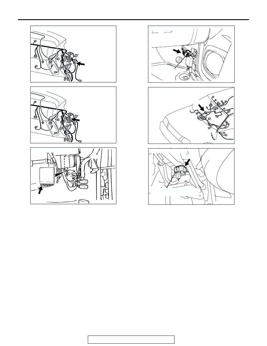
CONNECTOR: C-14
C-14
AK103911AC
CONNECTOR: C-79
C-79
AK103738AD
CONNECTOR: C-89
PCM
C-89(GR)
AK201000
MFI RELAY
CONNECTOR: C-59
AB
C-59
AK200018 AC
CONNECTOR: E-45
E-45(B)
AK200181
CONNECTOR: E-63
AB
E-63(B)
EVAPORATIVE EMISSION
VENTILATION SOLENOID