Mitsubishi Montero Sport (2004+). Manual - part 276


  Index      Mitsubishi     Mitsubishi Montero Sport - service repair manual 2004 year


Search            


Content   ..  274  275  276  277   ..


Mitsubishi Montero Sport (2004+). Manual - part 276


MULTIPORT FUEL INJECTION (MFI) DIAGNOSIS

TSB Revision

MULTIPORT FUEL INJECTION (MFI)

13A-517

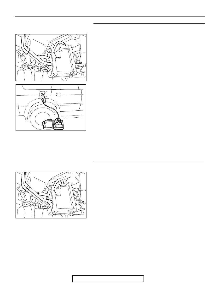
STEP 7. Pressure test the evaporative emission system 
lines between hoses E to hose L and the fuel tank.
(1) Disconnect hose E from the canister side, and plug the 

hose.

(2) Remove the fuel cap.

(3) Connect the evaporative emission system pressure pump 

to the fuel filler neck.

(4) Apply a pressure on the evaporative emission system 

pressure pump, and confirm that air is maintained.
NOTE: The "Pressure test" in this procedure refers to the 
I/M240 Simulation Test. The eight steps of this test are 
described in the manufacturer's instructions for the evapo-
rative emission system pressure pump, Miller number 
6872A.

(5) Disconnect the evaporative emission system pressure 

pump, and reinstall the fuel cap.

(6) Connect hose E to the evaporator line.
Q: Is the evaporative emission system line free of leaks?

YES : Go to Step 15 .
NO :  Go to Step 8 .

STEP 8. Check for vacuum leak in evaporative emission 
system hose E.
Perform a leakage test with a hand vacuum pump on hose E.
Q: Does the hose E hold vacuum?

YES : Go to Step 9 .
NO :  Replace the damaged hose. Then go to Step 16 .

AC005140

HOSE E

AC

ACX01358

AC004932

HOSE E

AH

MULTIPORT FUEL INJECTION (MFI) DIAGNOSIS

TSB Revision

MULTIPORT FUEL INJECTION (MFI)

13A-518

STEP 9. Pressure test the evaporative emission system 
lines between hoses F and J.
(1) Remove the fuel filler neck protector. (Refer to GROUP 

13B, Fuel Tank 

P.13B-6

).

(2) Perform a leakage test with a hand vacuum pump on hoses 

F, G, H, I and J.

Q: Do the hoses hold vacuum?

YES : Go to Step 10 .
NO :  Replace the damaged hose and reinstall the fuel filler 

neck protector. (Refer to GROUP 13B, Fuel Tank 

P.13B-6

). Then go to Step 16 .

STEP 10. Check the check valve A.
(1) Check valve A is a one-way check valve.
(2) Check valve A should allow air to flow in only one direction.
Q: Does check valve A allow air to press in one direction 

only?
YES : 
Go to Step 11 .
NO :  Replace it, and reinstall the fuel tank filler neck 

protector. (Refer to GROUP 13B, Fuel Tank 

P.13B-6

). 

Then go to Step 16 .

STEP 11. Check the check valve B.
(1) Check valve B is a one-way check valve.
(2) Check valve B should allow air to flow in only one direction.
Q: Does check valve B allow air to press in one direction 

only?
YES : 
Go to Step 12 .
NO :  Replace it, reinstall the fuel filler neck protector. 

(Refer to GROUP 13B, Fuel Tank

P.13B-6

). Then go 

to Step 16 .

AC004933AD

HOSE I

HOSE G

HOSE H

HOSE J

HOSE F

AC002076 AB

CHECK VALVE A

AC002078

CHECK VALVE B

AB

MULTIPORT FUEL INJECTION (MFI) DIAGNOSIS

TSB Revision

MULTIPORT FUEL INJECTION (MFI)

13A-519

STEP 12. Check for leaks in the evaporative emission 
system hose K and L.
(1) Remove the fuel tank. (Refer to GROUP 13B, Fuel Tank 

P.13B-6

).

(2) Perform a leakage test with a hand vacuum pump on hose 

k and L.

Q: Do the hoses hold vacuum?

YES : Go to Step 13 .
NO :  Replace the damaged hose, and reinstall the fuel 

tank. (Refer to GROUP 13B, Fuel Tank 

P.13B-6

). 

Then go to Step 16 .

STEP 13. Check for leaks in the fuel tank.
(1) Visually check for cracks and leaks, etc.

NOTE: Carefully check the fuel pump assembly and the 
inner pressure sensor installation section in the fuel tank.

AC004930

HOSE K

HOSE L

AC

AC005139

MULTIPORT FUEL INJECTION (MFI) DIAGNOSIS

TSB Revision

MULTIPORT FUEL INJECTION (MFI)

13A-520

(2) Connect the evaporative emission system pressure pump 

to the filler hose.

(3) Plug the fuel pump feed nipple, return hose, hose K and 

hose L connected to the fuel tank.
NOTE: If these items are not securely plugged here, the 
fuel could leak in the next step.

(4) Apply pressure with the evaporative emission system 

pressure pump.

(5) Pressurize the fuel tank with the evaporative emission 

system pressure pump.

(6) In the pressurized state, check for the leaks by applying 

soapy water solution to each section and look for bubbles.

Q: Are any leaks found?

YES <When there is a leak from the attachment points of 
the fuel pump assembly, the fuel tank differential 
pressure sensor or the fuel tank rollover valve.> : 

Reassemble the leaked parts and check again that 
there are no leaks. Then reinstall the fuel tank (Refer 
to GROUP 13B, Fuel Tank 

P.13B-6

). Then go to Step 

16 .

YES <When there is a leak from the fuel tank.> : Replace 

the fuel tank (Refer to GROUP 13B, Fuel Tank 

P.13B-6

). Then go to Step 16 .

NO :  When there is no leak, reinstall the fuel tank (Refer to 

GROUP 13B, Fuel Tank 

P.13B-6

). Then go to Step 14 

.

AC005138


Content   ..  274  275  276  277   ..