Mitsubishi Montero Sport (2004+). Manual - part 265


  Index      Mitsubishi     Mitsubishi Montero Sport - service repair manual 2004 year


Search            


Content   ..  263  264  265  266   ..


Mitsubishi Montero Sport (2004+). Manual - part 265


MULTIPORT FUEL INJECTION (MFI) DIAGNOSIS

TSB Revision

MULTIPORT FUEL INJECTION (MFI)

13A-473

STEP 3. Retest the system.
(1) Carry out a test drive with the drive cycle pattern. Refer to 

Diagnostic Function 

− OBD-II Drive Cycle − Procedure 6 − 

Other Monitor 

P.13A-4

.

(2) Check the diagnostic trouble code (DTC).
Q: Is DTC P0340 set?

YES : Replace the PCM. Then go to Step 18.
NO :  It can be assumed that this malfunction is intermittent. 

Refer to GROUP 00, How to Use 
Troubleshooting/Inspection Service Points 

P.00-7

.

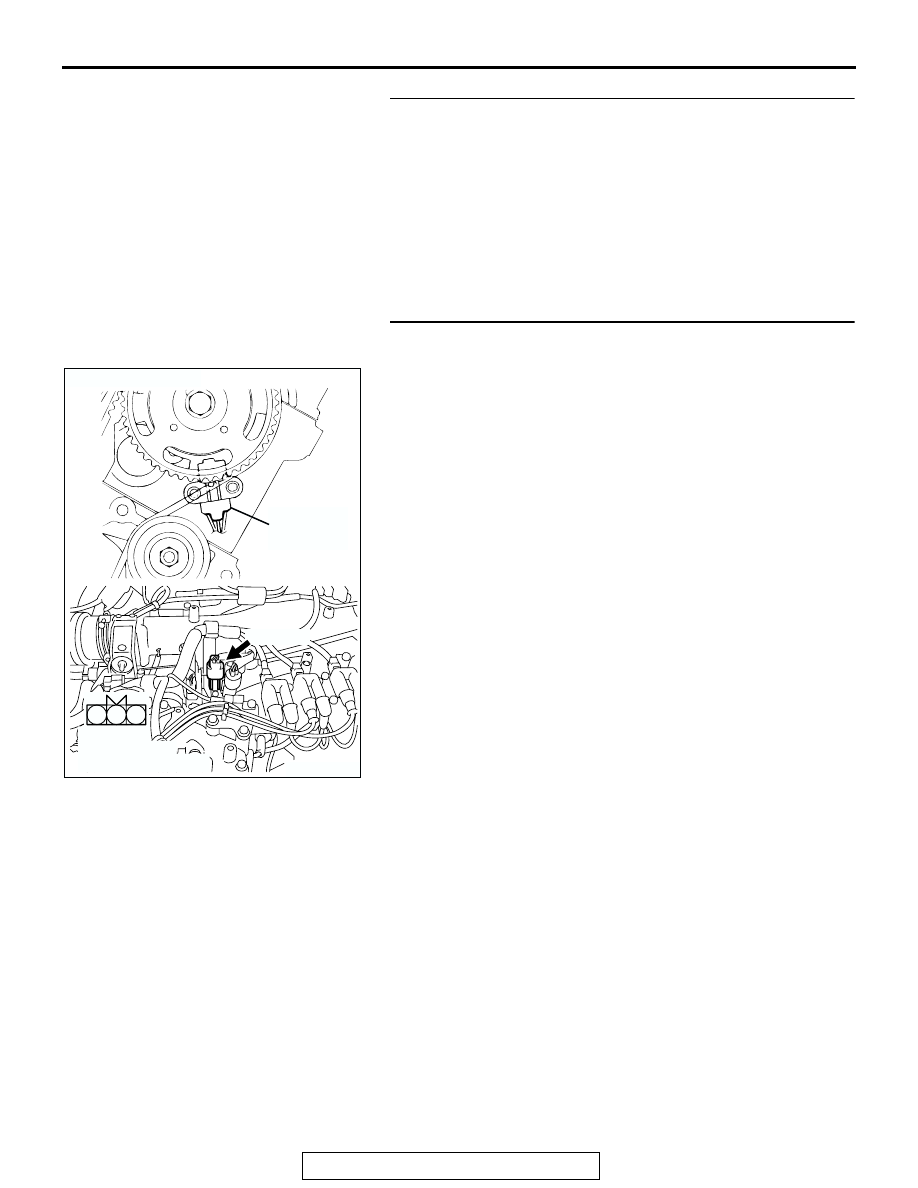
STEP 4. Check connector A-42 at camshaft position 
sensor for damage.
Q: Is the connector in good condition?

YES : Go to Step 5.
NO :  Repair or replace it. Refer to GROUP 00E, Harness 

Connector Inspection 

P.00E-2

. Then go to Step 18.

AK200488

1

2

3

AB

CONNECTOR: A-42

A-42(GR)

HARNESS 
CONNECTOR: 
COMPONENT SIDE

CAMSHAFT
POSITION
SENSOR

MULTIPORT FUEL INJECTION (MFI) DIAGNOSIS

TSB Revision

MULTIPORT FUEL INJECTION (MFI)

13A-474

STEP 5. Measure the sensor supply voltage at camshaft 
position sensor connector A-42.
(1) Disconnect the connector A-42 and measure at the harness 

side.

(2) Turn the ignition switch to the "ON" position.

(3) Measure the voltage between terminal No. 2 and ground.

• Voltage should be between 4.8 and 5.2 volts

(4) Turn the ignition switch to the "LOCK" (OFF) position.
Q: Is the measured voltage between 4.8 and 5.2 volts?

YES : Go to Step 10.
NO :  Go to Step 6.

AK200488

1

2

3

AB

CONNECTOR: A-42

A-42(GR)

HARNESS 
CONNECTOR: 
COMPONENT SIDE

CAMSHAFT
POSITION
SENSOR

AK000010

A-42 HARNESS 
CONNECTOR: 
COMPONENT SIDE

3 2 1

AF

MULTIPORT FUEL INJECTION (MFI) DIAGNOSIS

TSB Revision

MULTIPORT FUEL INJECTION (MFI)

13A-475

STEP 6. Measure the sensor supply voltage at PCM 
connector C-90 by backprobing.
(1) Do not disconnect the PCM connector C-90.
(2) Disconnect the camshaft position sensor connector A-42.
(3) Turn the ignition switch to the "ON" position.

(4) Measure the voltage between terminal No. 56 and ground 

by backprobing.

• Voltage should be between 4.8 and 5.2 volts.

(5) Turn the ignition switch to the "LOCK" (OFF) position.
Q: Is the measured voltage between 4.8 and 5.2 volts?

YES : Go to Step 7.
NO :  Go to Step 8.

STEP 7. Check connector C-90 at PCM for damage.
Q: Is the connector in good condition?

YES : Repair harness wire between camshaft position 

sensor connector A-42 (terminal No. 2) and PCM 
connector C-90 (terminal No. 56) because of open 
circuit. Then go to Step 18.

NO :  Repair or replace it. Refer to GROUP 00E, Harness 

Connector Inspection 

P.00E-2

. Then go to Step 18.

AK103762

42

43

48

49

50

51

52

53

54

55

56

57

46 45 44

58

59

60

61

62

63

64

65

66

47

41

AB

CONNECTOR: C-90

C-90(GR)

HARNESS CONNECTOR:
COMPONENT SIDE

AKX01545

41

AG

C-90 HARNESS CONNECTOR: 
HARNESS SIDE

42 43

44 45 46

47 48 49 50 51 52 53 54 55 56 57

58 59

60 61 62 63

64

66

AK103762

42

43

48

49

50

51

52

53

54

55

56

57

46 45 44

58

59

60

61

62

63

64

65

66

47

41

AB

CONNECTOR: C-90

C-90(GR)

HARNESS CONNECTOR:
COMPONENT SIDE

MULTIPORT FUEL INJECTION (MFI) DIAGNOSIS

TSB Revision

MULTIPORT FUEL INJECTION (MFI)

13A-476

STEP 8. Check connector C-90 at PCM for damage.
Q: Is the connector in good condition?

YES : Go to Step 9.
NO :  Repair or replace it. Refer to GROUP 00E, Harness 

Connector Inspection 

P.00E-2

. Then go to Step 18.

AK103762

42

43

48

49

50

51

52

53

54

55

56

57

46 45 44

58

59

60

61

62

63

64

65

66

47

41

AB

CONNECTOR: C-90

C-90(GR)

HARNESS CONNECTOR:
COMPONENT SIDE


Content   ..  263  264  265  266   ..