Mitsubishi Montero Sport (2004+). Manual - part 245


  Index      Mitsubishi     Mitsubishi Montero Sport - service repair manual 2004 year


Search            


Content   ..  243  244  245  246   ..


Mitsubishi Montero Sport (2004+). Manual - part 245


MULTIPORT FUEL INJECTION (MFI) DIAGNOSIS

TSB Revision

MULTIPORT FUEL INJECTION (MFI)

13A-393

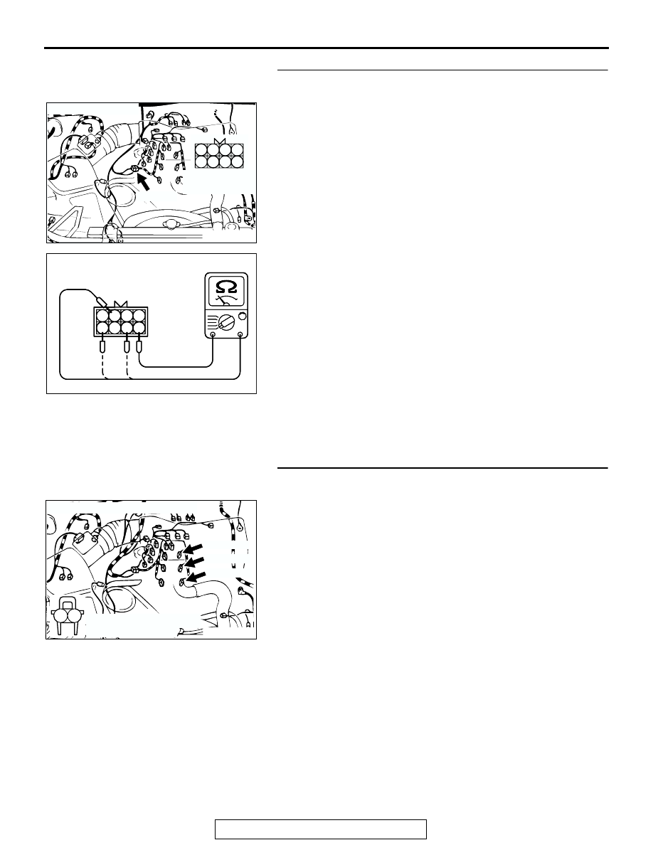
STEP 8. Check the left bank injector resistance at 
intermediate connector A-04.
(1) Disconnect the injector intermediate connector A-04.

(2) Measure the resistance between each injector side 

connector terminal.

a. Measure the resistance between terminal No. 8 and No. 

2 when measuring No.2 cylinder injector.

b. Measure the resistance between terminal No. 8 and No. 

7 when measuring No.4 cylinder injector.

c. Measure the resistance between terminal No. 8 and No. 

5 when measuring No.6 cylinder injector.

• Resistance should be between 13 and 16 ohms [at 20°C 

(68

°F)].

Q: Is the measured resistance between 13 and 16 ohms [at 

20

°C (68°F)]?

YES : Go to Step 11.
NO :  Go to Step 9.

STEP 9. Check harness connector A-70, A-71, A-72 at left 
bank injector for damage.
(1) Check the injector connector, which deviates from the 

standard value at Step 8.

Q:  Is the harness connector in good condition?

YES : Then go to Step 10.
NO :  Repair or replace it. Refer to GROUP 00E, Harness 

Connector Inspection 

P.00E-2

. Then go to Step 16.

AK200014

7

2 1
6 5

4 3
8

CONNECTOR: A-04

AB

FEMALE SIDE 
CONNECTOR

A-04(B)

AK000533

6

3 4
7 8

1 2
5

AK000533

6

3 4
7 8

1 2
5

INJECTOR
INTERMEDIATE
CONNECTOR

AB

AK200016

1

2

AB

CONNECTORS: A-70, A-71, A-72

A-70(GR)

A-71(GR)

A-72(GR)

HARNESS CONNECTOR: 
COMPONENT SIDE

MULTIPORT FUEL INJECTION (MFI) DIAGNOSIS

TSB Revision

MULTIPORT FUEL INJECTION (MFI)

13A-394

STEP 10. Check the left bank injector.
(1) Remove the intake manifold.
(2) Disconnect the left bank injector connector, which deviates 

from the standard value at Step 8.

(3) Measure the resistance between injector side connector 

terminal No. 1 and No. 2.

Standard value: 13 

 16 ohms [at 20°C (68°F)]

Q: Is the resistance between 13 and 16 ohms [at 20

°

(68

°F)]?

YES : Repair harness wire between injector intermediate 

connector and left bank injector connector because of 
harness damage. Then go to Step 16.

NO :  Replace the injector. Then go to Step 16.

STEP 11. Check harness connector C-89 at PCM for 
damage.
Q: Is the harness connector in good condition?

YES : Go to Step 12.
NO :  Repair or replace it. Refer to GROUP 00E, Harness 

Connector Inspection 

P.00E-2

. Then go to Step 16.

AK200016

1

2

AB

CONNECTORS: A-70, A-71, A-72

A-70(GR)

A-71(GR)

A-72(GR)

HARNESS CONNECTOR: 
COMPONENT SIDE

AKX01414AB

INJECTOR SIDE
CONNECTOR

1 2

AK103914

2

3

4

5

6

7

8

9

11

12

13

14

15

16

17

18

19

20

30

21

22

23

24

25

26

27

28

29

31

32

33

34

35

1

10

AB

CONNECTOR: C-89

C-89(GR)

HARNESS CONNECTOR:
COMPONENT SIDE

MULTIPORT FUEL INJECTION (MFI) DIAGNOSIS

TSB Revision

MULTIPORT FUEL INJECTION (MFI)

13A-395

STEP 12. Check for harness damage between left bank 
injector connector and PCM connector.

a. Check the harness wire between injector connector A-72 

(terminal No. 2) and PCM connector C-89 (terminal No. 9) 
when checking No. 2 cylinder injector.

b. Check the harness wire between injector connector A-71 

(terminal No. 2) and PCM connector C-89 (terminal No. 2) 
when checking No. 4 cylinder injector.

c. Check the harness wire between injector connector A-70 

(terminal No. 2) and PCM connector C-89 (terminal No. 25) 
when checking No. 6 cylinder injector.

Q: Is the harness wire in good condition?

YES : Go to Step 13.
NO :  Repair it. Then go to Step 16.

STEP 13. Check the fuel pressure.
Refer to On-vehicle Service 

− Fuel Pressure Test 

P.13A-884

.

Q: Are there any abnormalities?

YES : Go to Step 14.
NO :  Repair or replace it. Then go to Step 16.

STEP 14. Check for entry of foreign matter (water, 
kerosene, etc.) into fuel.
Q: Are there any abnormalities?

YES : Go to Step 15.
NO :  Replace the fuel. Then go to Step 16.

STEP 15. Replace the left bank injector.
(1) Replace the left bank injector.
(2) Carry out a test drive with the drive cycle pattern. Refer to 

Diagnostic Function 

− OBD-II Drive Cycle − Procedure 2 − 

Fuel Trim Monitor 

P.13A-4

.

(3) Read in the diagnostic trouble code (DTC).
Q: Is DTC P0174 set?

YES : Replace the PCM. Then go to Step 16.
NO :  The procedure is complete.

AK200016

1

2

AB

CONNECTORS: A-70, A-71, A-72

A-70(GR)

A-71(GR)

A-72(GR)

HARNESS CONNECTOR: 
COMPONENT SIDE

AK103914

2

3

4

5

6

7

8

9

11

12

13

14

15

16

17

18

19

20

30

21

22

23

24

25

26

27

28

29

31

32

33

34

35

1

10

AB

CONNECTOR: C-89

C-89(GR)

HARNESS CONNECTOR:
COMPONENT SIDE

AK200016

1

2

AB

CONNECTORS: A-70, A-71, A-72

A-70(GR)

A-71(GR)

A-72(GR)

HARNESS CONNECTOR: 
COMPONENT SIDE

MULTIPORT FUEL INJECTION (MFI) DIAGNOSIS

TSB Revision

MULTIPORT FUEL INJECTION (MFI)

13A-396

STEP 16. Test the OBD-II drive cycle.
(1) Carry out a test drive with the drive cycle pattern. Refer to 

Diagnostic Function 

− OBD-II Drive Cycle − Procedure 2 − 

Fuel Trim Monitor 

P.13A-4

.

(2) Check the diagnostic trouble code (DTC).
Q: Is DTC P0174 set?

YES : Repeat the troubleshooting.
NO :  The procedure is complete.

DTC P0175: System too Rich (bank 1)

.

Fuel Trim Circuit

• Refer to DTC P0201 − P0206, Injector Circuit. 

P.13A-428

.

CIRCUIT OPERATION

• Refer to DTC P0201 − P0206, Injector Circuit. 

P.13A-428

.

TECHNICAL DESCRIPTION

• If a malfunction occurs in the fuel system, the fuel 

trim value becomes too small.

• The PCM checks whether the fuel trim value is 

within a specified range.

.

DESCRIPTIONS OF MONITOR METHODS
Left bank air/fuel learning value (long term fuel trim) 

and air/fuel feedback integral value (short term 
fuel trim) are too rich.

.

MONITOR EXECUTION
Continuous

.

MONITOR EXECUTION CONDITIONS (Other 
monitor and Sensor)

Other Monitor (There is no temporary DTC stored 

in memory for the item monitored below)

• Misfire monitor

Sensor (The sensor below is determined to be 

normal)

• Volume airflow sensor

• Engine coolant temperature sensor 

• Intake air temperature sensor

• Barometric pressure sensor

• Throttle position sensor

.


Content   ..  243  244  245  246   ..