Mitsubishi Montero Sport (2004+). Manual - part 231


  Index      Mitsubishi     Mitsubishi Montero Sport - service repair manual 2004 year


Search            


Content   ..  229  230  231  232   ..


Mitsubishi Montero Sport (2004+). Manual - part 231


MULTIPORT FUEL INJECTION (MFI) DIAGNOSIS

TSB Revision

MULTIPORT FUEL INJECTION (MFI)

13A-337

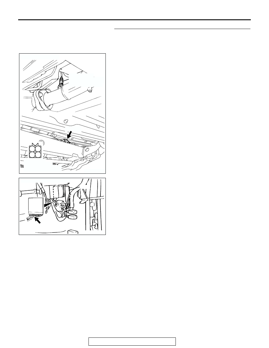
STEP 9. Check for open circuit and harness damage 
between left bank heated oxygen sensor (rear) connector 
E-48 (terminal No. 2) and PCM connector C-90 (terminal 
No. 57).

NOTE: Check harness after checking intermediate connector 
C-71, C-79 and E-45. If intermediate connector C-71, C-79 and 
E-45 is damaged, repair or replace it. Refer to GROUP 00E, 
Harness Connector Inspection 

P.00E-2

. Then go to Step 11.

Q: Is the harness wire in good condition?

YES : Replace the PCM. Then go to Step 11.
NO :  Repair it. Then go to Step 11.

AK200498

1

2

3

4

E-48(B)

AB

CONNECTOR: E-48

HARNESS 
CONNECTOR: 
COMPONENT SIDE

LEFT BANK
HEATED OXYGEN
SENSOR (REAR)

AK103738AC

CONNECTOR: C-90

PCM

C-90(GR)

MULTIPORT FUEL INJECTION (MFI) DIAGNOSIS

TSB Revision

MULTIPORT FUEL INJECTION (MFI)

13A-338

STEP 10. Check the left bank heated oxygen sensor (rear).
(1) Disconnect the left bank heated oxygen sensor (rear) 

connector E-48 and connect test harness special tool, 
MD998464, to the connector on the left bank heated oxygen 
sensor (front) side.

(2) Warm up the engine until engine coolant 80

°C (176°F) or 

higher.

(3) Perform a tracing for 5 minutes or more with the engine 

speed of 4,500 r/min.

(4) Connect a digital volt meter between terminal No. 2 (black 

clip) and terminal No. 4 (white clip).

(5) While repeatedly revving the engine, measure the left bank 

heated oxygen sensor (rear) output voltage.

Standard value: 0.6 

 1.0 volt

CAUTION

• Be very careful when connecting the jumper wire; 

incorrect connection can damage the oxygen sensor.

• Be careful the heater is broken when voltage of beyond 

12 volts is applied to the oxygen sensor heater.
NOTE: If the sufficiently high temperature (of approximate 
400

°

C or more) is not reached although the oxygen sensor 

is normal, the output voltage would be possibly low 
although the rich air-fuel ratio. Therefore, if the output volt-
age is low, use a jumper wire to connect the terminal No.2 
and the terminal No. 1 of the oxygen sensor with a (+) termi-
nal and (-) terminal of 12 volts power supply respectively, 
then check again.

Q: Is the voltage between 0.6 and 1.0 volt?

YES : Replace the PCM. Then go to Step 11.
NO :  Replace the left bank heated oxygen sensor (rear). 

Then go to Step 11.

AK200498

1

2

3

4

E-48(B)

AB

CONNECTOR: E-48

HARNESS 
CONNECTOR: 
COMPONENT SIDE

LEFT BANK
HEATED OXYGEN
SENSOR (REAR)

AKX01624

HEATED
OXYGEN
SENSOR
COMPONENT
SIDE
CONNECTOR

MD998464

WHITE

BLACK

AL

MULTIPORT FUEL INJECTION (MFI) DIAGNOSIS

TSB Revision

MULTIPORT FUEL INJECTION (MFI)

13A-339

STEP 11. Test the OBD-II drive cycle.
(1) Carry out a test drive with the drive cycle pattern. Refer to 

Diagnostic Function 

− OBD-II Drive Cycle − Procedure 6 − 

Other Monitor 

P.13A-4

.

(2) Check the diagnostic trouble code (DTC).
Q: Is DTC P0156 set?

YES : Repeat the troubleshooting.
NO :  The procedure is complete.

MULTIPORT FUEL INJECTION (MFI) DIAGNOSIS

TSB Revision

MULTIPORT FUEL INJECTION (MFI)

13A-340

DTC P0157: Heated Oxygen Sensor Circuit Low Voltage (bank 2, sensor 2)

AK303392

Left Bank Heated Oxygen Sensor (rear) Circuit

BL

ACK

BL

ACK

BL

ACK

BL

ACK

WHITE

BL

ACK

BL

ACK

BL

ACK

WHITE

WHITE

BL

ACK

-RED

BL

ACK

-RED

POWERTRAIN CONTROL MODULE (PCM)

1

10

15

2

11

3

12

4

13 14

5

16

6

17

7

18

8

19

9

20

E-44

73

57

19

5

16

10

12

8

2

7

4

2

3

1

C-91

C-90

FROM MFI RELAY

TO PCM

LEFT BANK HEATED
OXYGEN SENSOR (REAR)

1

10

15

2

11

3

12

4

13 14

5

16

6

17

7

18

8

19

9

20

E-45

E-45

47

41

42 43

48 49 50 51 52 53 54 55 56 57

46

45

44

58

59

60 61 62 63

64 65 66

C-90
(MU803781)

1

10

2 3 4 5 6 7 8 9

11

12 13 14 15 16 17 18 19 20 21 22

23 24 25 26 27 28 29 30 31 32 33

C-71

71

76

77

72 73 74

75

79 80

78

81

87 88

89

91

90

92

97

98

82

93

83

94

84 85

95

86

96

C-91
(MU803782)

1 2
3 4

E-48
MU802605

6

10

2

7

8

3 4 5

9

11 12 13

1

C-79
MU801553

JOINT
CONNECTOR (4)


Content   ..  229  230  231  232   ..