Mitsubishi Montero Sport (2004+). Manual - part 214


  Index      Mitsubishi     Mitsubishi Montero Sport - service repair manual 2004 year


Search            


Content   ..  212  213  214  215   ..


Mitsubishi Montero Sport (2004+). Manual - part 214


MULTIPORT FUEL INJECTION (MFI) DIAGNOSIS

TSB Revision

MULTIPORT FUEL INJECTION (MFI)

13A-269

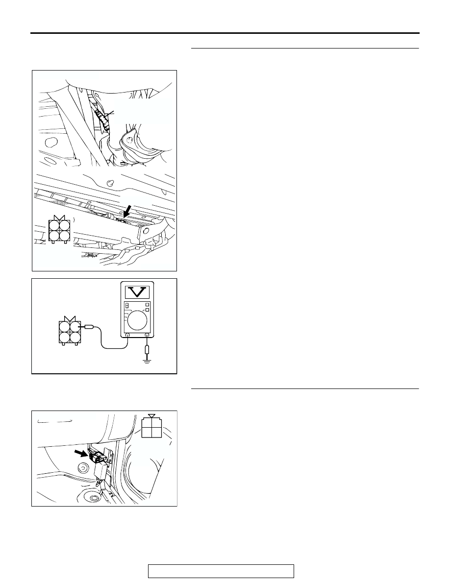
STEP 3. Measure the power supply voltage at right bank 
heated oxygen sensor (rear) harness side connector E-47.
(1) Disconnect the connector E-47 and measure at the harness 

side.

(2) Turn the ignition switch to the "ON" position.

(3) Measure the voltage between terminal No. 1 and ground.

• Voltage should be battery positive voltage.

(4) Turn the ignition switch to the "LOCK" (OFF) position.
Q: Is battery positive voltage (approximately 12 volts) 

present?
YES : 
Go to Step 5.
NO :  Go to Step 4.

STEP 4. Check harness connector C-59 at the MFI relay for 
damage.
Q: Is the connector in good condition?

YES :  Check connector C-14, C-79 and E-45 at 

intermediate connector for damage, and repair or 
replace as required. Refer to GROUP 00E, Harness 
Connector Inspection 

P.00E-2

. If intermediate 

connector is in good condition, repair harness wire 
between MFI relay connector C-59 (terminal No. 1) 
and right bank heated oxygen sensor (rear) connector 
E-47 (terminal No. 1) because of open circuit or short 
circuit to ground. Then go to Step 12.

NO :  Repair or replace it. Refer to GROUP 00E, Harness 

Connector Inspection 

P.00E-2

. Then go to Step 12.

AK200492

1

2

3

4

E-47(GR)

AB

CONNECTOR: E-47

HARNESS 
CONNECTOR: 
COMPONENT SIDE

RIGHT BANK
HEATED OXYGEN
SENSOR (REAR)

AKX01496

2

1

4

3

E-47 HARNESS 
CONNECTOR: 
COMPONENT SIDE

AU

AK200023

2 1

3

4

CONNECTOR: C-59

AB

C-59

HARNESS 
CONNECTOR:
COMPONENT 
SIDE

MULTIPORT FUEL INJECTION (MFI) DIAGNOSIS

TSB Revision

MULTIPORT FUEL INJECTION (MFI)

13A-270

STEP 5. Measure the power supply voltage at PCM 
connector C-89 by backprobing.
(1) Do not disconnect the connector C-89.
(2) Turn the ignition switch to the "ON" position.

(3) Measure the voltage between terminal No. 27 and ground 

by backprobing.

• Voltage should be battery positive voltage.

(4) Turn the ignition switch to the "LOCK" (OFF) position.
Q: Is battery positive voltage (approximately 12 volts) 

present?
YES : 
Go to Step 8.
NO :  Go to Step 6.

STEP 6. Check connector C-89 at PCM for damage.
Q: Is the connector in good condition?

YES : Go to Step 7.
NO :  Repair or replace it. Refer to GROUP 00E, Harness 

Connector Inspection 

P.00E-2

. Then go to Step 12.

AK103914

2

3

4

5

6

7

8

9

11

12

13

14

15

16

17

18

19

20

30

21

22

23

24

25

26

27

28

29

31

32

33

34

35

1

10

AB

CONNECTOR: C-89

C-89(GR)

HARNESS CONNECTOR:
COMPONENT SIDE

AKX01537

AKX01537

1

2

3 4

5 6

7 8

10 11 12 13 14 15 16 17 18 19 20 21 22 23

24 25

26 27 28 29

30 31 32 33

34 35

C-89 HARNESS CONNECTOR: 
HARNESS SIDE

AH

9

AK103914

2

3

4

5

6

7

8

9

11

12

13

14

15

16

17

18

19

20

30

21

22

23

24

25

26

27

28

29

31

32

33

34

35

1

10

AB

CONNECTOR: C-89

C-89(GR)

HARNESS CONNECTOR:
COMPONENT SIDE

MULTIPORT FUEL INJECTION (MFI) DIAGNOSIS

TSB Revision

MULTIPORT FUEL INJECTION (MFI)

13A-271

STEP 7. Check for open circuit or short circuit to ground 
between right bank heated oxygen sensor (rear) connector 
E-47 (terminal No. 3) and PCM connector C-89 (terminal 
No. 27).

NOTE: Check harness after checking intermediate connector 
C-79 and E-45. If intermediate connectors are damaged, repair 
or replace them. Refer to GROUP 00E, Harness Connector 
Inspection 

P.00E-2

. Then go to Step 12.

Q: Is the harness wire in good condition?

YES : Replace the PCM. Then go to Step 12.
NO :  Repair it. Then go to Step 12.

AK200492

1

2

3

4

E-47(GR)

AB

CONNECTOR: E-47

HARNESS 
CONNECTOR: 
COMPONENT SIDE

RIGHT BANK
HEATED OXYGEN
SENSOR (REAR)

AK103914

2

3

4

5

6

7

8

9

11

12

13

14

15

16

17

18

19

20

30

21

22

23

24

25

26

27

28

29

31

32

33

34

35

1

10

AB

CONNECTOR: C-89

C-89(GR)

HARNESS CONNECTOR:
COMPONENT SIDE

MULTIPORT FUEL INJECTION (MFI) DIAGNOSIS

TSB Revision

MULTIPORT FUEL INJECTION (MFI)

13A-272

STEP 8. Check connector C-89 at PCM for damage.
Q: Is the connector in good condition?

YES : Go to Step 9.
NO :  Repair or replace it. Refer to GROUP 00E, Harness 

Connector Inspection 

P.00E-2

. Then go to Step 12.

STEP 9. Check for harness damage between MFI relay 
connector C-59 (terminal No. 1) and right bank heated 
oxygen sensor (rear) connector E-47 (terminal No. 1).

AK103914

2

3

4

5

6

7

8

9

11

12

13

14

15

16

17

18

19

20

30

21

22

23

24

25

26

27

28

29

31

32

33

34

35

1

10

AB

CONNECTOR: C-89

C-89(GR)

HARNESS CONNECTOR:
COMPONENT SIDE

AK200023

2 1

3

4

CONNECTOR: C-59

AB

C-59

HARNESS 
CONNECTOR:
COMPONENT 
SIDE

AK200492

1

2

3

4

E-47(GR)

AB

CONNECTOR: E-47

HARNESS 
CONNECTOR: 
COMPONENT SIDE

RIGHT BANK
HEATED OXYGEN
SENSOR (REAR)


Content   ..  212  213  214  215   ..