Mitsubishi Montero Sport (2004+). Manual - part 206


  Index      Mitsubishi     Mitsubishi Montero Sport - service repair manual 2004 year


Search            


Content   ..  204  205  206  207   ..


Mitsubishi Montero Sport (2004+). Manual - part 206


MULTIPORT FUEL INJECTION (MFI) DIAGNOSIS

TSB Revision

MULTIPORT FUEL INJECTION (MFI)

13A-237

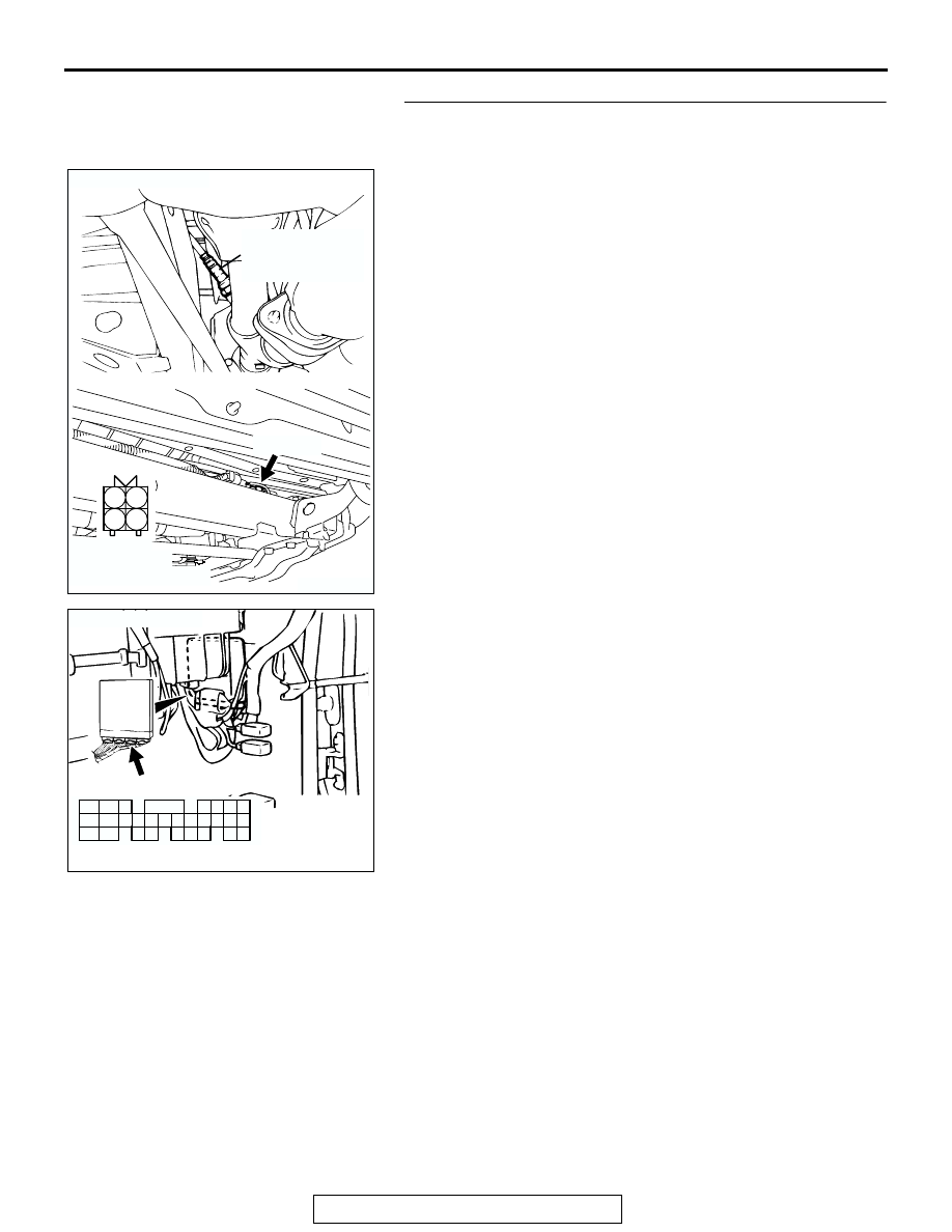
STEP 4. Check for open circuit between right bank heated 
oxygen sensor (rear) connector E-47 (terminal No. 4) and 
PCM connector C-91 (terminal No. 74).

NOTE: Check harness after checking intermediate connector 
C-79, E-45. If intermediate connector is damaged, repair or 
replace it. Refer to GROUP 00E, Harness Connector Inspec-
tion 

P.00E-2

. Then go to Step 11.

Q: Is the harness wire in good condition?

YES : Go to Step 5.
NO :  Repair it. Then go to Step 11.

AK200492

1

2

3

4

E-47(GR)

AB

CONNECTOR: E-47

HARNESS 
CONNECTOR: 
COMPONENT SIDE

RIGHT BANK
HEATED OXYGEN
SENSOR (REAR)

AK104028

98

78

71

88

89

76

77

72
79
91

73
80

74

75

81
92

82

83

93

84

85

94

86

87

95

96

90

97

AB

CONNECTOR: C-91

C-91(GR)

HARNESS CONNECTOR:
COMPONENT SIDE

MULTIPORT FUEL INJECTION (MFI) DIAGNOSIS

TSB Revision

MULTIPORT FUEL INJECTION (MFI)

13A-238

STEP 5. Using scan tool MB991958, check data list item 69: 
Heated Oxygen Sensor Bank 1, Sensor 2 (right rear).

CAUTION

To prevent damage to scan tool MB991958, always turn the 
ignition switch to the "LOCK" (OFF) position before con-
necting or disconnecting scan tool MB991958.
(1) Connect scan tool MB991958 to the data link connector.
(2) Start the engine and run at idle.
(3) Set scan tool MB991958 to the data reading mode for item 

69, Heated Oxygen Sensor Bank 1, Sensor 2 (right rear).

• Warm up the engine. When the engine is revved, the 

output voltage should repeat 0 volt and 0.6 to 1.0 volt 
alternately.

(4) Turn the ignition switch to the "LOCK" (OFF) position.
Q: Is the sensor operating properly?

YES : It can be assumed that this malfunction is intermittent. 

Refer to GROUP 00, How to Use 
Troubleshooting/Inspection Service Points 

P.00-7

.

NO :  Replace the PCM. Then go to Step 11.

STEP 6. Check connector E-47 at right bank heated oxygen 
sensor (rear) for damage.
Q: Is the connector in good condition?

YES : Go to Step 7.
NO :  Repair or replace it. Refer to GROUP 00E, Harness 

Connector Inspection 

P.00E-2

. Then go to Step 11.

AK303629AB

MB991911

MB991827

MB991824 

16-PIN

AK200492

1

2

3

4

E-47(GR)

AB

CONNECTOR: E-47

HARNESS 
CONNECTOR: 
COMPONENT SIDE

RIGHT BANK
HEATED OXYGEN
SENSOR (REAR)

MULTIPORT FUEL INJECTION (MFI) DIAGNOSIS

TSB Revision

MULTIPORT FUEL INJECTION (MFI)

13A-239

STEP 7. Check for continuity at right bank heated oxygen 
sensor (rear) harness side connector E-47.
(1) Disconnect the connector E-47 and measure at the harness 

side.

(2) Check for the continuity between terminal No. 2 and 

ground.

• Should be less than 2 ohms.

Q: Does continuity exist?

YES : Go to Step 10.
NO :  Go to Step 8.

STEP 8. Check connector C-90 at PCM for damage.
Q: Is the connector in good condition?

YES : Go to Step 9.
NO :  Repair or replace it. Refer to GROUP 00E, Harness 

Connector Inspection 

P.00E-2

. Then go to Step 11.

AK200492

1

2

3

4

E-47(GR)

AB

CONNECTOR: E-47

HARNESS 
CONNECTOR: 
COMPONENT SIDE

RIGHT BANK
HEATED OXYGEN
SENSOR (REAR)

AK000243AO

E-47 HARNESS 
CONNECTOR: 
COMPONENT SIDE

2 1

4 3

AK103762

42

43

48

49

50

51

52

53

54

55

56

57

46 45 44

58

59

60

61

62

63

64

65

66

47

41

AB

CONNECTOR: C-90

C-90(GR)

HARNESS CONNECTOR:
COMPONENT SIDE

MULTIPORT FUEL INJECTION (MFI) DIAGNOSIS

TSB Revision

MULTIPORT FUEL INJECTION (MFI)

13A-240

STEP 9. Check for open circuit between right bank heated 
oxygen sensor (rear) connector E-47 (terminal No. 2) and 
PCM connector C-90 (terminal No. 57).

NOTE: Check harness after checking intermediate connector 
C-71, C-79 and E-45. If intermediate connectors are damaged, 
repair or replace it. Refer to GROUP 00E, Harness Connector 
Inspection 

P.00E-2

. Then go to Step 11.

Q: Is the harness wire in good condition?

YES : Replace the PCM. Then go to Step 11.
NO :  Repair it. Then go to Step 11.

AK200492

1

2

3

4

E-47(GR)

AB

CONNECTOR: E-47

HARNESS 
CONNECTOR: 
COMPONENT SIDE

RIGHT BANK
HEATED OXYGEN
SENSOR (REAR)

AK103762

42

43

48

49

50

51

52

53

54

55

56

57

46 45 44

58

59

60

61

62

63

64

65

66

47

41

AB

CONNECTOR: C-90

C-90(GR)

HARNESS CONNECTOR:
COMPONENT SIDE


Content   ..  204  205  206  207   ..