Mitsubishi Montero Sport (2004+). Manual - part 169


  Index      Mitsubishi     Mitsubishi Montero Sport - service repair manual 2004 year


Search            


Content   ..  167  168  169  170   ..


Mitsubishi Montero Sport (2004+). Manual - part 169


MULTIPORT FUEL INJECTION (MFI) DIAGNOSIS

TSB Revision

MULTIPORT FUEL INJECTION (MFI)

13A-89

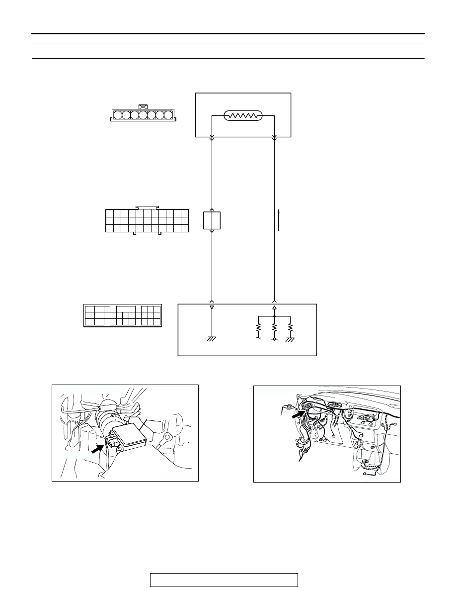
DTC P0111: Intake Air Temperature Circuit Range/Performance Problem

AK301863

Intake Air Temperature Sensor Circuit

RED

-BL

UE

BL

ACK

BL

ACK

57

5

5V

POWERTRAIN CONTROL MODULE (PCM)

INTAKE AIR TEMPERATURE SENSOR
(INCORPORATED IN VOLUME 
AIRFLOW SENSOR)

12

6

64

15

1 2 3 4 5 6 7

A-01

1

10

2 3 4 5 6 7 8 9

11

12 13 14 15 16 17 18 19 20 21 22

23 24 25 26 27 28 29 30 31 32 33

C-71

47

41

42 43

48 49 50 51 52 53 54 55 56 57

46

45

44

58

59

60 61 62 63

64 65 66

C-90
(MU803781)

JOINT
CONNEC-
TOR (4)

AK103908

CONNECTOR: A-01

INTAKE AIR 
TEMPERATURE
SENSOR

A-01(B)

AD

AK103912AB

CONNECTOR: C-71

C-71

MULTIPORT FUEL INJECTION (MFI) DIAGNOSIS

TSB Revision

MULTIPORT FUEL INJECTION (MFI)

13A-90

.

CIRCUIT OPERATION

• Approximately 5 volts are applied to the intake air 

temperature sensor output terminal (terminal No. 
6) from the PCM (terminal No. 64) via the resistor 
in the PCM. The ground terminal (terminal No. 5) 
is grounded with PCM (terminal No. 57).

• The intake air temperature sensor is a negative 

temperature coefficient type of resistor. When the 
intake air temperature rises, the resistance 
decreases.

• The intake air temperature sensor output voltage 

increases when the resistance increases and 
decreases when the resistance decreases.

.

TECHNICAL DESCRIPTION

• The intake air temperature sensor converts the 

intake air temperature to a voltage.

• The PCM checks whether this voltage is within a 

specified range.

.

DESCRIPTIONS OF MONITOR METHODS
Intake air temperature sensor output voltage does 

not change when specified go/stop operations 
are repeated.

.

MONITOR EXECUTION
Continuous

.

MONITOR EXECUTION CONDITIONS (Other 
monitor and Sensor)

Other Monitor (There is no temporary DTC stored 

in memory for the item monitored below)

• Not applicable

Sensor (The sensor below is determined to be 

normal)

• Not applicable

.

AK103738AC

CONNECTOR: C-90

PCM

C-90(GR)

MULTIPORT FUEL INJECTION (MFI) DIAGNOSIS

TSB Revision

MULTIPORT FUEL INJECTION (MFI)

13A-91

DTC SET CONDITIONS

Logic Flow Chart

.

Check Conditions

• Engine coolant temperature is higher than 76°C 

(169

°F).

• Repeat 5 or more times: drive

*1

, stop

*2

.

Drive

*1

: vehicle speed higher than 50 km/h (31 

mph) lasting a total of more than 60 seconds.

Stop

*2

: vehicle speed lower than 1.5 km/h (0.9 

mph) lasting more than 30 seconds.

Judgement Criteria

• Changes in the intake air temperature is lower 

than 1

°C (1.8°F).

.

OBD-II DRIVE CYCLE PATTERN
Refer to Diagnostic Function 

− OBD-II Drive Cycle − 

Procedure 6 

− Other Monitor 

P.13A-4

.

.

TROUBLESHOOTING HINTS (The most likely 
causes for this code to be set are:)

• Intake air temperature sensor failed.

• Harness damage in intake air temperature sensor 

circuit, or connector damage.

• PCM failed.

END

YES

NO

NO

NO

START

MONITORING

CONDITION

YES

MALFUNCTION

GOOD

F1: COUNTER OF A DRIVING STATE.
F2: COUNTER OF A STOP STATE.

INTAKE AIR TEMP.

CHANGES

GO/STOP OPERATION

FOR SPECIFIED TIMES

YES

AK301423

MULTIPORT FUEL INJECTION (MFI) DIAGNOSIS

TSB Revision

MULTIPORT FUEL INJECTION (MFI)

13A-92

DIAGNOSIS

Required Special Tools:

• MB991958: Scan Tool (MUT-III Sub Assembly)

• MB991824: V.C.I

• MB991827: USB Cable

• MB991911: Main Harness B

STEP 1. Using scan tool MB991958, check data list item 13: 
Intake Air Temperature Sensor.

CAUTION

To prevent damage to scan tool MB991958, always turn the 
ignition switch to the "LOCK" (OFF) position before con-
necting or disconnecting scan tool MB991958.
(1) Connect scan tool MB991958 to the data link connector.
(2) Remove the air intake hose from the volume airflow sensor.
(3) Turn the ignition switch to the "ON" position.
(4) Set scan tool MB991958 to the data reading mode for item 

13, Intake Air Temperature Sensor.

(5) Heating the sensor using a hair drier.

• The indicated temperature increases.

NOTE: Do not allow it to increase over 80

°

C (176

°

F).

(6) Turn the ignition switch to the "LOCK" (OFF) position.
(7) Attach the air intake hose.
Q: Is the sensor operating properly?

YES : It can be assumed that this malfunction is intermittent. 

Refer to GROUP 00, How to Use 
Troubleshooting/Inspection Service Points 

P.00-7

.

NO :  Go to Step 2.

AK303629AB

MB991911

MB991827

MB991824 

16-PIN

AKX01621 AB

INTAKE AIR
TEMPERATURE
SENSOR


Content   ..  167  168  169  170   ..