Mitsubishi Montero Sport (2004+). Manual - part 111


  Index      Mitsubishi     Mitsubishi Montero Sport - service repair manual 2004 year


Search            


Content   ..  109  110  111  112   ..


Mitsubishi Montero Sport (2004+). Manual - part 111


AUTO-CRUISE CONTROL

TSB Revision

ENGINE AND EMISSION CONTROL

17-39

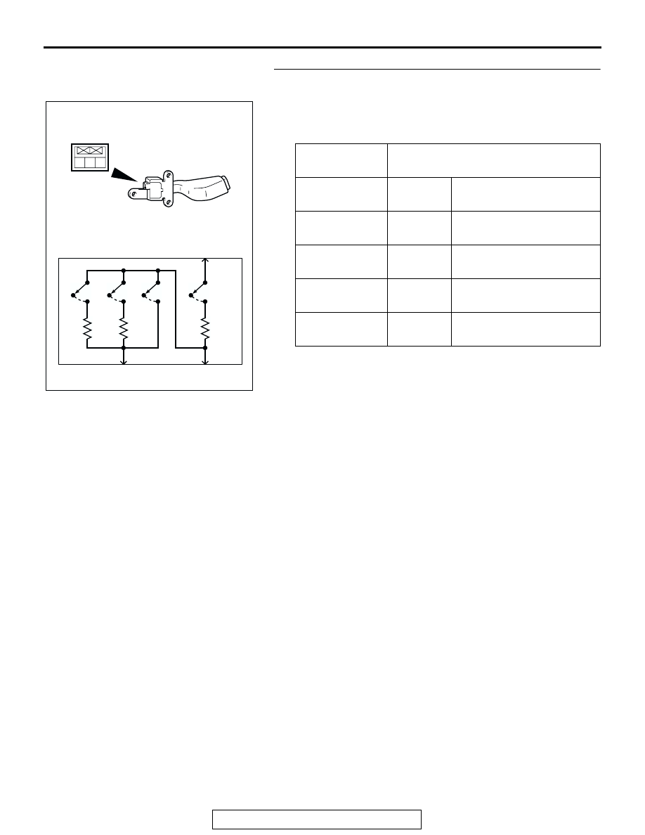
STEP 8. Check the auto-cruise control switch.
(1) Remove the auto-cruise control switch 

P.17-99

.

(2) Measure the resistance at between the terminals when 

each of the "SET," "RESUME," "CANCEL" and "MAIN" 
switch is pressed.

Q: Is the values measured correspond to those in the table 

below?
YES : 
Go to Step 14 .
NO :  Replace the auto-cruise control switch. (Refer to 

P.17-99

). Then go to Step 15 .

SWITCH 
POSITION

RESISTANCE BETWEEN TERMINALS

MAIN switch 
"OFF"

Terminal 1 
and 2

Less than 2 ohms

MAIN switch 
"ON"

Terminal 1 
and 2

Approximately 3.9 k

"CANCEL" 
switch "ON"

Terminal 2 
and 3

Approximately 0 

"RESUME" 
switch "ON"

Terminal 2 
and 3

Approximately 910 

"SET" switch 
"ON"

Terminal 2 
and 3

Approximately 220 

1 2 3

AC102096AB

OFF

OFF

OFF

OFF

ON

ON

ON

ON

CAN

MAIN

RES

SET

1

2

3

AUTO-CRUISE CONTROL

TSB Revision

ENGINE AND EMISSION CONTROL

17-40

STEP 9. Measure the output circuit voltage at auto-cruise 
control-ECU connector C-35 by backprobing.
(1) Do not disconnect auto-cruise control-ECU connector C-35.
(2) Turn the ignition switch to the "ON" position.

(3) Measure the voltage between auto-cruise control-ECU 

connector C-35 terminal 12 and ground by backprobing.

• Voltage should be battery positive voltage. (The MAIN 

switch is at the "ON" position.)

(4) Measure the voltage between auto-cruise control-ECU 

connector C-35 terminal 9 and ground by backprobing.

• Voltage should measure between 6.8 and 7.2 volts. 

(MAIN switch is at the "ON" position.)

• Voltage should measure between 3.5 and 5.0 volts. (All 

switches are at the "OFF" position.)

• Voltage should measure between 0.4 and 2.3 volts. 

("SET" switch is at the "ON" position.)

• Voltage should measure between 2.3 and 3.5 volts. 

("RESUME" switch is at the "ON" position.)

• Voltage should measure 1 volt or less. ("CANCEL" 

switch is at the "ON" position.)

(5) Turn the ignition switch to the "LOCK" (OFF) position.
Q: Is the voltage within specifications?

YES : Go to Step 14 .
NO :  Go to Step 10 .

STEP 10. Check auto-cruise control-ECU connector C-35 
for loose, corroded or damaged terminals, or terminals 
pushed back in the connector.
Q: Is the connector damaged?

YES : Repair or replace the damaged components. (Refer 

to GROUP 00E, Harness Connector Inspection 

P.00E-2

). Then go to Step 15 .

NO :  Go to Step 11 .

AC202155

2

3

10

11

5

6

13

14

12

4

8

16 15

7

9

1

C-35 (B)

AB

CONNECTOR: C-35

C-35 HARNESS SIDE 
CONNECTOR

1 2 3 4 5 6 7 8

9 10 11 12 13 14 15 16

ACX01900

C-35 HARNESS CONNECTOR:
HARNESS SIDE

AH

AC202155

2

3

10

11

5

6

13

14

12

4

8

16 15

7

9

1

C-35 (B)

AB

CONNECTOR: C-35

C-35 HARNESS SIDE 
CONNECTOR

AUTO-CRUISE CONTROL

TSB Revision

ENGINE AND EMISSION CONTROL

17-41

STEP 11. Check the clock spring.
Refer to GROUP 52B, Air Bag Modules and Clock Spring 

P.52B-84

.

Q: Is the clock spring damaged?

YES : Replace the clock spring. (Refer to GROUP 52B, Air 

Bag Modules and Clock Spring 

P.52B-84

). Then go to 

Step 15 .

NO :  Go to Step 12 .

STEP 12. Check auto-cruise control switch connector 
D-19, clock spring connector D-25 for loose, corroded or 
damaged terminals, or terminals pushed back in the 
connector.
Q: Is any connector damaged?

YES : Repair or replace the damaged components. (Refer 

to GROUP 00E, Harness Connector Inspection 

P.00E-2

). Then go to Step 15 .

NO :  Go to Step 13 .

STEP 13. Check the harness wire between auto-cruise 
control switch connector D-19 (terminal No.2 and 3) and 
auto-cruise control-ECU connector C-35 (terminal No.9 
and 12).
Q: Is any harness wire between auto-cruise control switch 

connector D-19 (terminal No.2 and 3) and auto-cruise 
control-ECU connector C-35 (terminal No.9 and 12) 
damaged?
YES : 
Repair the damaged harness wire. Then go to Step 

15 .

NO :  It can be assumed that this malfunction is intermittent. 

(Refer to GROUP 00, How to Use 
Troubleshooting/Inspection Service Points 

− How to 

Cope with Intermittent Malfunction 

P.00-7

).

AC202306

4

3

1 2

1 2 3

AB

CONNECTORS: D-19, D-25

D-19 (Y)

D-25

D-19 (Y)

D-25

1

3

4

2 1

3

HARNESS 
CONNECTOR

AC203151

3 2 1

CONNECTOR: D-19

AB

D-19 (Y)

D-19: 
HARNESS 
SIDE CONNECTOR

AC202155

2

3

10

11

5

6

13

14

12

4

8

16 15

7

9

1

C-35 (B)

AB

CONNECTOR: C-35

C-35 HARNESS SIDE 
CONNECTOR

AUTO-CRUISE CONTROL

TSB Revision

ENGINE AND EMISSION CONTROL

17-42

STEP 14. Check the diagnostic trouble codes.
Q: Is DTC 15 set?

YES : Replace the auto-cruise control-ECU. (Refer to 

P.17-99

). Then go to Step 15 .

NO :  It can be assumed that this malfunction is intermittent. 

(Refer to GROUP 00, How to Use 
Troubleshooting/Inspection Service Points 

− How to 

Cope with Intermittent Malfunction 

P.00-7

).

STEP 15. Check the diagnostic trouble codes.
Q: Is DTC 15 set?

YES : Return to Step 1 .
NO :  This procedure is complete.

DTC 16: Auto-cruise Control-ECU

.

DTC SET CONDITIONS
This code is output when a problem is found on the 
cancel status hold circuit or microcomputer operation 
monitor circuit, which is incorporated in the 
auto-cruise control-ECU.

.

TROUBLESHOOTING HINTS
Malfunction of the auto-cruise control-ECU.

DIAGNOSIS

Replace the auto-cruise control-ECU. (Refer to 

P.17-99

). Then 

check that DTC 16 is not set.


Content   ..  109  110  111  112   ..