Mitsubishi Montero (2004+). Manual - part 979


  Index      Mitsubishi     Mitsubishi Montero - service repair manual 2004 year


Search            


Content   ..  977  978  979  980   ..


Mitsubishi Montero (2004+). Manual - part 979


TRANSFER DIAGNOSIS <ACTIVE TRAC AWD II>

TSB Revision

AUTOMATIC TRANSMISSION

23A-491

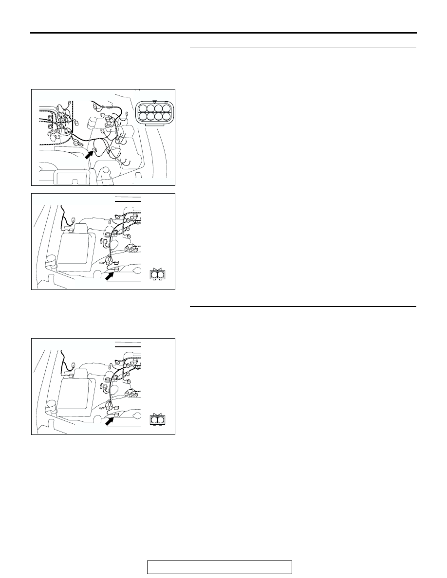
STEP 13. Check intermediate connector B-27 and 
free-wheel engage switch connector B-39 for loose, 
corroded or damaged terminals, or terminals pushed back 
in the connector.
Q: Are the connectors and terminals in good condition?

YES : Go to Step 14.
NO :  Repair or replace the damaged components. Refer to 

GROUP 00E, Harness Connector Inspection 

P.00E-2

.

STEP 14. Check harness for open circuit between 
free-wheel engage switch connector B-39 terminal 1 and 
ground.
Q: Is the harness wire in good condition?

YES : Go to Step 15.
NO :  Repair or replace the harness wire.

AC204169

CONNECTOR : B-27

AD

B-27 (B)

8

4

7

3

5

1

6

2

AC204168

CONNECTOR : B-39

AC

B-39 (GR)

2

1

AC204168

CONNECTOR : B-39

AC

B-39 (GR)

2

1

TRANSFER DIAGNOSIS <ACTIVE TRAC AWD II>

TSB Revision

AUTOMATIC TRANSMISSION

23A-492

STEP 15. Using scan tool MB991958, check data list item 
38: Free-wheel Engage Switch.

CAUTION

To prevent damage to scan tool MB991958, always turn the 
ignition switch to the "LOCK" (OFF) position before con-
necting or disconnecting scan tool MB991958.
(1) Connect scan tool MB991958 to the data link connector.
(2) Turn the ignition switch to the "ON" position.
(3) Transmission range should be "N" range.
(4) See scan tool MB991958 to data reading mode.

• Item 38: Free-wheel Engage Switch.

• When the transfer shift lever position is other than 

2H, the display should be "ON."

• When the transfer shift lever position is 2H, the dis-

play should be "OFF."

(5) Turn the ignition switch to the "LOCK" (OFF) position.
Q: Is the switch operating properly?

YES : It can be assumed that this malfunction is intermittent. 

Refer to GROUP 00, How to Use 
Troubleshooting/Inspection Service Points 

− How to 

Cope with Intermittent Malfunction 

P.00-6

.

NO :  Replace the transfer-ECU.

DTC 41: Shift Actuator System (Short/Open Circuit)

AC307591 AC

MB991911

MB991824

MB991827

AC307591

DATA LINK

CONNECTOR

AC100559

Shift Actuator System Circuit

AB

TRANSFER DIAGNOSIS <ACTIVE TRAC AWD II>

TSB Revision

AUTOMATIC TRANSMISSION

23A-493

.

CIRCUIT OPERATION
When voltage is applied to the shift actuator terminal 
2 from the transfer-ECU, the motor turns to the nor-
mal direction and the drive mode is shifted in the 
order of 2H 

→ 4H → 4HLc → 4LLc. When voltage is 

applied to the shift actuator terminal 1, the motor 
turns to the reverse direction and the drive mode is 
shifted in the order of 4LLc 

→ 4HLc → 4H → 2H.

.

DTC SET CONDITIONS
In the case that the transfer-ECU terminal voltage is 
more than the main relay voltage (90% of specified 
voltage) or lower than the main relay voltage (10% of 
specified voltage) when the shift is not operated, 
DTC 41 is set as the open circuit or the short circuit 
of the shift actuator system.

.

TROUBLESHOOTING HINTS (THE MOST LIKELY 
CAUSES FOR THIS CODE TO BE SET ARE:)

• Malfunction of the shift actuator

• Damaged harness, connector

• Malfunction of the transfer-ECU

DIAGNOSIS

Required Special Tool:

• MB991958: Scan Tool (MUT-III Sub Assembly)

• MB991824: V.C.I.

• MB991827: MUT-III USB Cable

• MB991911: MUT-III Main Harness B

AC204395

CONNECTOR : C-09

AH

C-09 (GR)

2

1

AC204176

CONNECTOR : E-109

BB

11 12

25

24

13

26

9

22

7

6

20

19

8

21

10

23

5

4

17

2

1

15

14

3

16

18

TRANSFER DIAGNOSIS <ACTIVE TRAC AWD II>

TSB Revision

AUTOMATIC TRANSMISSION

23A-494

STEP 1. Using scan tool MB991958, check data list item 12: 
Shift Actuator Voltage.

CAUTION

To prevent damage to scan tool MB991958, always turn the 
ignition switch to the "LOCK" (OFF) position before con-
necting or disconnecting scan tool MB991958.
(1) Connect scan tool MB991958 to the data link connector.
(2) Turn the ignition switch to the "ON" position.
(3) Transmission range should be "N" range.
(4) Set scan tool MB991958 to data reading mode.

• Item 12: Shift Actuator Voltage.

• When the operating transfer shift lever 2H → 4H, 4H 

→ 4HLc or 4HLc → 4LLc, the display should be 1/2 

battery voltage 

→ battery positive voltage → 1.0 volt 

or less 

→ 1/2 battery voltage.

• When the operating transfer shift lever 4LLc → 

4HLc, 4HLc 

→ 4H or 4H → 2H, the display should 

be 1/2 battery voltage 

→ 1.0 volt or less → 1/2 bat-

tery voltage.

(5) Turn the ignition switch to the "LOCK" (OFF) position.
Q: Is the actuator operating properly?

YES : It can be assumed that this malfunction is intermittent. 

Refer to GROUP 00, How to Use 
Troubleshooting/Inspection Service Points 

− How to 

Cope with Intermittent Malfunction 

P.00-6

 .

NO :  Go to Step 2.

AC307591 AC

MB991911

MB991824

MB991827

AC307591

DATA LINK

CONNECTOR


Content   ..  977  978  979  980   ..