Mitsubishi Montero (2004+). Manual - part 952


  Index      Mitsubishi     Mitsubishi Montero - service repair manual 2004 year


Search            


Content   ..  950  951  952  953   ..


Mitsubishi Montero (2004+). Manual - part 952


AUTOMATIC TRANSMISSION DIAGNOSIS

TSB Revision

AUTOMATIC TRANSMISSION

23A-383

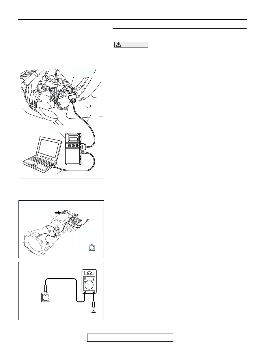
STEP 9. Using scan tool MB991958, check data list item 75: 
4LLc Detection Switch.

CAUTION

To prevent damage to scan tool MB991958, always turn the 
ignition switch to the "LOCK" (OFF) position before con-
necting or disconnecting scan tool MB991958.
(1) Connect scan tool MB991958 to the data link connector.
(2) Turn the ignition switch to the "ON" position.
(3) Set scan tool MB991958 to data reading mode.

• Item 75: 4LLc Detection Switch.

• When the transfer shift lever position is 4LLc, scan 

tool MB991958 display should be "ON."

• When the transfer shift lever position is other than 

4LLc, scan tool MB991958 display should be "OFF."

(4) Turn the ignition switch to the "LOCK" (OFF) position.
Q: Is the switch operating properly?

YES : It can be assumed that this malfunction is intermittent. 

Refer to GROUP 00, How to Use 
Troubleshooting/Inspection Service Points 

− How to 

Cope with Intermittent Malfunction 

P.00-6

.

NO :  Replace the PCM.

STEP 10. Measure the resistance at 4LLc detection switch 
connector C-05.
(1) Disconnect connector C-05 and measure at the switch side.
(2) Turn the ignition switch to the "ON" position.
(3) Transmission range should be "N" range.

(4) Check for the continuity between terminal 1 and ground.

• When the transfer shift lever position is 4LLc there 

should measure less than 2 ohms.

• When the transfer shift lever position is other than 4LLc 

there should be open circuit.

(5) Turn the ignition switch to the "LOCK" (OFF) position.
Q: Is the resistance 2 ohms?

YES : Go to Step 11.
NO :  Replace the 4LLc detection switch. Refer to GROUP 

23B, Transfer 

P.23B-75

.

AC307591 AC

MB991911

MB991824

MB991827

AC307591

DATA LINK

CONNECTOR

AC204395

CONNECTOR : C-05

AG

C-05 (BR)

C-05

1

AC204918

C-05 HARNESS CONNECTOR : 
4LLc DETECTION SWITCH SIDE

DA

1

AUTOMATIC TRANSMISSION DIAGNOSIS

TSB Revision

AUTOMATIC TRANSMISSION

23A-384

STEP 11. Check PCM connector D-133 for loose, corroded 
or damaged terminals, or terminals pushed back in the 
connector.
Q: Are the connector and terminals in good condition?

YES : Go to Step 9.
NO :  Repair or replace the damaged components. Refer to 

GROUP 00E, Harness Connector Inspection 

P.00E-2

.

AC204681AD

CONNECTOR: D-133

D-133 (GR)

31 32

33 34

35 36 37 38 39 40 41 42 43
44 45 46 47 48 49

50 51

52 53

54 55 56

57 58

Continue

DATA LIST REFERENCE TABLE

TSB Revision

AUTOMATIC TRANSMISSION

23A-385

23A

DATA LIST REFERENCE TABLE

M1231109100111

MUT-III 
SCAN TOOL 
DISPLAY

ITEM 
NO.

INSPECTION ITEM INSPECTION REQUIREMENT

NORMAL 
CONDITION

2ND SOL 
DUTY

33

Second solenoid 
valve duty %

Transmission 
range: Sport mode

Driving at constant 
speed of 10 km/h 
(6.2 mph) in 1st gear

100%

Transmission 
range: Sport mode

Driving at constant 
speed of 30 km/h (19 
mph) in 2nd gear

0%

Transmission 
range: Sport mode

Driving at constant 
speed of 50 km/h (31 
mph) in 3rd gear

100%

Transmission 
range: Sport mode

Driving at constant 
speed of 50 km/h (31 
mph) in 4th gear

100%

Transmission 
range: Sport mode

Driving at constant 
speed of 70 km/h (44 
mph) in 5th gear

0%

A/T CONT 
RLY

54

A/T control relay 
output voltage

Ignition switch: ON

Battery positive 
voltage

CKP 
SENSOR

21

Crankshaft position 
sensor

• Engine: Idling 

(after the 
worming up)

• Transmission 

range: P

Accelerator pedal: 
Fully closed

600 

− 900 r/min

Accelerator pedal: 
Depressed

Gradually rises 
from the above 
value

DUAL 
PRESS SW

65

Dual pressure switch

• Engine: Idling

• Transmission 

range: P, N

A/C switch: ON 
(While the A/C 
compressor is in 
operation)

ON

A/C switch: OFF

OFF

ENGINE 
LOAD

57

Engine load 
(volumetric 
efficiency)

• Engine: Idling

• Transmission 

range: N

Accelerator pedal: 
fully closed 

→ 

depressed

Data changes

ISS SENSOR 22

Input shaft speed 
sensor

Gear range: 4th 
gear

Driving at constant 
speed of 50 km/h (31 
mph)

1,400 

− 1,700 

r/min

L/R SOL 
DUTY

31

Low-reverse 
solenoid valve duty 
%

Transmission 
range: Sport mode

Driving at constant 
speed of 10 km/h 
(6.2 mph) in 1st gear

0%

Transmission 
range: Sport mode

Driving at constant 
speed of 30 km/h (19 
mph) in 2nd gear

100%

DATA LIST REFERENCE TABLE

TSB Revision

AUTOMATIC TRANSMISSION

23A-386

Transmission 
range: Sport mode

Driving at constant 
speed of 50 km/h (31 
mph) in 3rd gear

100%

Transmission 
range: Sport mode

Driving at constant 
speed of 50 km/h (31 
mph) in 4th gear

0%

Transmission 
range: Sport mode

Driving at constant 
speed of 70 km/h (44 
mph) in 5th gear

0%

O/D SOL 
DUTY

34

Overdrive solenoid 
valve duty %

Transmission 
range: Sport mode

Driving at constant 
speed of 10 km/h 
(6.2 mph) in 1st gear

100%

Transmission 
range: Sport mode

Driving at constant 
speed of 30 km/h (19 
mph) in 2nd gear

100%

Transmission 
range: Sport mode

Driving at constant 
speed of 50 km/h (31 
mph) in 3rd gear

0%

Transmission 
range: Sport mode

Driving at constant 
speed of 50 km/h (31 
mph) in 4th gear

0%

Transmission 
range: Sport mode

Driving at constant 
speed of 70 km/h (44 
mph) in 5th gear

0%

OD OFF 
SIGNAL

66

Overdrive off signal 
(Auto-cruise ECM 
signal)

While auto-cruise 
is engaged

Level road

OFF

Uphill grade

ON

OSS 
SENSOR

23

Output shaft speed 
sensor

Gear range: 4th 
gear

Driving at constant 
speed of 50 km/h (31 
mph)

1,400 

− 1,700 

r/min

TR SWITCH

61

Transmission range 
switch

Ignition switch: ON Transmission range: 

P

P

Transmission range: 
R

R

Transmission range: 
N

N

Transmission range: 
D

D

MUT-III 
SCAN TOOL 
DISPLAY

ITEM 
NO.

INSPECTION ITEM INSPECTION REQUIREMENT

NORMAL 
CONDITION


Content   ..  950  951  952  953   ..