Mitsubishi Montero (2004+). Manual - part 898


  Index      Mitsubishi     Mitsubishi Montero - service repair manual 2004 year


Search            


Content   ..  896  897  898  899   ..


Mitsubishi Montero (2004+). Manual - part 898


AUTOMATIC TRANSMISSION DIAGNOSIS

TSB Revision

AUTOMATIC TRANSMISSION

23A-167

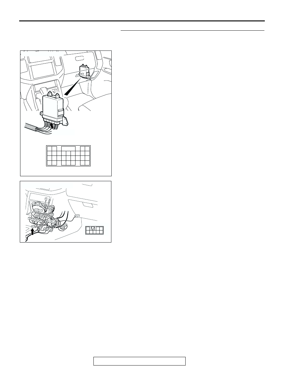
STEP 24. Check the harness for damage between PCM 
connector D-134 terminal 85 and shift switch assembly 
connector E-115 terminal 4.
Q: Is the harness wire in good condition?

YES : Go to Step 25.
NO :  Repair or replace the harness wire.

AC204681AC

CONNECTOR: D-134

D-134 (GR)

61 62

63 64

65 66 67 68 69 70 71 72 73

82

89

81

88

80

79

78

77

87

86

85

76

75

74

84

83

AC204176

CONNECTOR : E-115

BE

8

3

4 5

1

2

6 7

AUTOMATIC TRANSMISSION DIAGNOSIS

TSB Revision

AUTOMATIC TRANSMISSION

23A-168

STEP 25. Using scan tool MB991958, check data list item 
61: Transmission Range Switch.

CAUTION

To prevent damage to scan tool MB991958, always turn the 
ignition switch to the "LOCK" (OFF) position before con-
necting or disconnecting scan tool MB991958.
(1) Connect scan tool MB991958 to the data link connector.
(2) Turn the ignition switch to the "ON" position.
(3) Set scan tool MB991958 to the data reading mode.

• Item 61: Transmission Range Switch.

• Move the selector lever to "P," "R," "N," "D" and sport 

mode positions and confirm that the selected trans-
mission ranges match the positions (Sport mode is 
indicated as "D" on scan tool MB991958).

(4) Turn the ignition switch to the "LOCK" (OFF) position.
Q: Is the switch operating properly?

YES : It can be assumed that this malfunction is intermittent. 

Refer to GROUP 00, How to Use 
Troubleshooting/Inspection Service Points 

− How to 

Cope with Intermittent Malfunction 

P.00-6

.

NO :  Replace the PCM.

AC307591 AC

MB991911

MB991824

MB991827

AC307591

DATA LINK

CONNECTOR

AUTOMATIC TRANSMISSION DIAGNOSIS

TSB Revision

AUTOMATIC TRANSMISSION

23A-169

DTC 29 (P0500): Vehicle Speed Sensor System

AC205193 AB

Vehicle Speed Sensor System Circuit

AC204170

CONNECTOR : D-03

CE

D-03 (GR)

58

57

67

66

56

54 55

64

59

53

52

62

61

63

65

60

51

AC204171

CONNECTOR : D-116

AN

9 10

8

6 7

31 32

30

29

18 19 20 21

5

4

2

1

3

27

26

24

23

25

12 13 14 15 16 17

28

11
22
33

AUTOMATIC TRANSMISSION DIAGNOSIS

TSB Revision

AUTOMATIC TRANSMISSION

23A-170

.

CIRCUIT OPERATION

• 4.8 − 5.2 volts voltage is applied to the vehicle 

speed sensor from the PCM (terminal 79). The 
vehicle speed sensor generates a pulse signal 
when the output terminal is opened and ground.

• The PCM compares the vehicle speed sensor 

signal to input shaft and output shaft speed sen-
sor signals.

• If the vehicle speed sensor becomes inoperative, 

the transmission will not shift normally.

.

DESCRIPTIONS OF MONITOR METHODS
If there is no detection pulse from vehicle speed sen-
sor even when output shaft revolution equals or 
exceeds specified value, PCM judges that vehicle 
speed sensor has a failure.

.

MONITOR EXECUTION
Continuous

.

MONITOR EXECUTION CONDITIONS (OTHER 
MONITOR AND SENSOR)

Other Monitor (There is no temporary DTC stored 

in memory for the item monitored below)

• DTC 23 (P0720): Output shaft speed sensor mal-

function

Sensor (The sensor below is determined to be 

normal)

• Output shaft speed sensor

.

AC204681AC

CONNECTOR: D-134

D-134 (GR)

61 62

63 64

65 66 67 68 69 70 71 72 73

82

89

81

88

80

79

78

77

87

86

85

76

75

74

84

83

AC204176

CONNECTOR : E-111

BF

15

4

14

37

36

26 27

12

11

35

34

23 24

3

13

25

9

2

8

32

20 21

6

5

17

29

30

18

1

7

19

31

10

22

33

16

28

38


Content   ..  896  897  898  899   ..