Mitsubishi Montero (2004+). Manual - part 888


  Index      Mitsubishi     Mitsubishi Montero - service repair manual 2004 year


Search            


Content   ..  886  887  888  889   ..


Mitsubishi Montero (2004+). Manual - part 888


AUTOMATIC TRANSMISSION DIAGNOSIS

TSB Revision

AUTOMATIC TRANSMISSION

23A-127

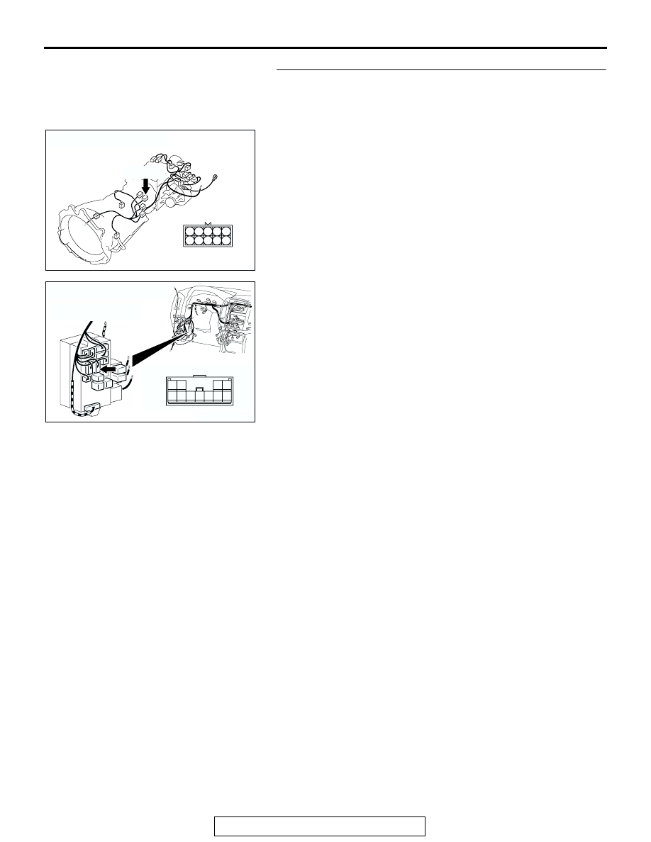
STEP 4. Check harness for open circuit or short circuit to 
ground between transmission range switch connector 
C-04 terminal 7 and junction block connector D-212 
terminal 9.
Q: Is the harness wire in good condition?

YES : Go to Step 5.
NO :  Repair or replace the harness wire.

AC204395

CONNECTOR : C-04

AF

C-04 (B)

4
9

5

10

3
8

2
7

6

1

AC204173

CONNECTOR : D-212

AZ

3

10

9

4

11

8

7

1

5

2

6

JUNCTION BLOCK
(FRONT VIEW)

AUTOMATIC TRANSMISSION DIAGNOSIS

TSB Revision

AUTOMATIC TRANSMISSION

23A-128

STEP 5. Using scan tool MB991958, check data list item 61: 
Transmission Range Switch.

CAUTION

To prevent damage to scan tool MB991958, always turn the 
ignition switch to the "LOCK" (OFF) position before con-
necting or disconnecting scan tool MB991958.
(1) Connect scan tool MB991958 to the data link connector.
(2) Turn the ignition switch to the "ON" position.
(3) Set scan tool MB991958 to the data reading mode.

• Item 61: Transmission Range Switch.

• Move the selector lever to "P," "R," "N," "D" and sport 

mode positions and confirm that the selected trans-
mission ranges match the positions shown on scan 
tool MB991958 (Sport mode is indicated as "D" on 
scan tool MB991958).

(4) Turn the ignition switch to the "LOCK" (OFF) position.
Q: Is the switch operating properly?

YES : It can be assumed that this malfunction is intermittent. 

Refer to GROUP 00, How to Use 
Troubleshooting/Inspection Service Points 

− How to 

Cope with Intermittent Malfunction 

P.00-6

.

NO :  Replace the PCM.

STEP 6. Check the transmission range switch.
Measure the resistance between the terminals for each trans-
mission range as indicated in the table below.

Q: Is the measured resistance less than 2 ohms for each 

transmission range?
YES : 
Go to Step 7.
NO :  Replace the transmission range switch. Refer to 

GROUP 23B, Transmission 

P.23B-14

.

AC307591 AC

MB991911

MB991824

MB991827

AC307591

DATA LINK

CONNECTOR

TRANSMISSION 
RANGE

TERMINAL 
CONNECTION OF 
TESTER

SPECIFIED 
CONDITION

P

− 7

Less than 2 ohms.

R

− 8

N

− 7

D

− 7

ACX01187AD

P

R

N

D

AUTOMATIC TRANSMISSION DIAGNOSIS

TSB Revision

AUTOMATIC TRANSMISSION

23A-129

STEP 7. Check transmission range switch connector C-04 
for loose, corroded or damaged terminals, or terminals 
pushed back in the connector.
Q: Are the connector and terminals in good condition?

YES : Go to Step 8.
NO :  Repair or replace the damaged components. Refer to 

GROUP 00E, Harness Connector Inspection 

P.00E-2

.

STEP 8. Measure the transmission range switch output 
voltage at PCM connector D-134 by backprobing.
(1) Do not disconnect connector D-134.
(2) Turn the ignition switch to the "ON" position.
(3) Move the selector lever to the "P" position.

(4) Measure the voltage between terminal 66 and ground by 

backprobing.

• The voltage should measure battery positive voltage.

(5) Turn the ignition switch to the "LOCK" (OFF) position.
Q: Is the measured voltage battery positive voltage?

YES : Go to Step 13.
NO :  Go to Step 9.

AC204395

CONNECTOR : C-04

AF

C-04 (B)

4
9

5

10

3
8

2
7

6

1

AC204681AC

CONNECTOR: D-134

D-134 (GR)

61 62

63 64

65 66 67 68 69 70 71 72 73

82

89

81

88

80

79

78

77

87

86

85

76

75

74

84

83

AC204918 BF

D-134 HARNESS CONNECTOR : 
HARNESS SIDE

76

85

65

72

71

73

82

75

81

74

63 64

66

70

69

68

67

78

87

79

88 89

80

77

86

62

61

83 84

AUTOMATIC TRANSMISSION DIAGNOSIS

TSB Revision

AUTOMATIC TRANSMISSION

23A-130

STEP 9. Check PCM connector D-134 and intermediate 
connector E-114 for loose, corroded or damaged 
terminals, or terminals pushed back in the connector.
Q: Are the connectors and terminals in good condition?

YES : Go to Step 10.
NO :  Repair or replace the damaged components. Refer to 

GROUP 00E, Harness Connector Inspection 

P.00E-2

.

AC204681AC

CONNECTOR: D-134

D-134 (GR)

61 62

63 64

65 66 67 68 69 70 71 72 73

82

89

81

88

80

79

78

77

87

86

85

76

75

74

84

83

AC204176

CONNECTOR : E-114

BD

38

28

16

33

22

10

31

19

7

1

18

30

29

17

5

6

21

20

32

8

2

9

25

13

3

24

23

3435

1112

27

26

3637

14

4

15


Content   ..  886  887  888  889   ..