Mitsubishi Montero (2004+). Manual - part 869


  Index      Mitsubishi     Mitsubishi Montero - service repair manual 2004 year


Search            


Content   ..  867  868  869  870   ..


Mitsubishi Montero (2004+). Manual - part 869


AUTOMATIC TRANSMISSION DIAGNOSIS

TSB Revision

AUTOMATIC TRANSMISSION

23A-51

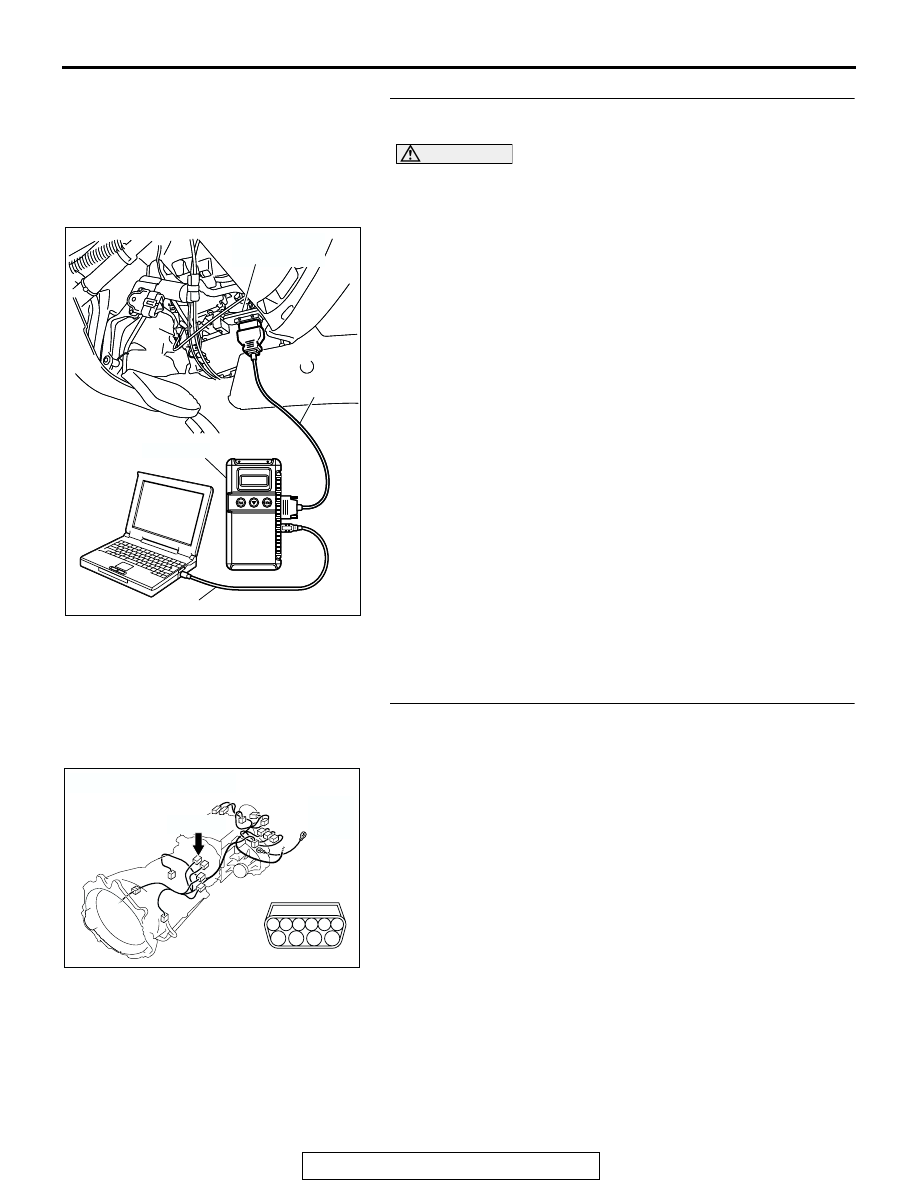
STEP 6. Using scan tool MB991958, check data list item 15: 
Transmission Fluid Temperature Sensor.

CAUTION

To prevent damage to scan tool MB991958, always turn the 
ignition switch to the "LOCK" (OFF) position before con-
necting or disconnecting scan tool MB991958.
(1) Connect scan tool MB991958 to the data link connector.
(2) Start the engine.
(3) Set scan tool MB991958 to the data reading mode.

• Item 15: Transmission Fluid Temperature Sensor.

• When the engine is cool: Almost equal to the ambi-

ent temperature (atmospheric temperature)
NOTE: Set scan tool MB991958 to the data reading 
mode for item number 13, Intake Air Temperature 
(IAT) Sensor and note the temperature measure-
ment. When the engine is cool, the temperature 
should be almost equal to the ambient temperature 
(atmospheric temperature), and the IAT sensor mea-
surement should be approximately the same as the 
Transmission Fluid Temperature Sensor.

• When the engine is warm: 70 to 80°C (158 to 

176

°F).

(4) Turn the ignition switch to the "LOCK" (OFF) position.
Q: Is the sensor operating properly?

YES : It can be assumed that this malfunction is intermittent. 

Refer to GROUP 00, How to Use 
Troubleshooting/Inspection Service Points 

− How to 

Cope with Intermittent Malfunction 

P.00-6

.

NO :  Replace the PCM.

STEP 7. Check A/T control solenoid valve assembly 
connector C-03 for loose, corroded or damaged terminals, 
or terminals pushed back in the connector.
Q: Are the connector and terminals in good condition?

YES : Go to Step 8.
NO :  Repair or replace the damaged components. Refer to 

GROUP 00E, Harness Connector Inspection 

P.00E-2

.

AC307591 AC

MB991911

MB991824

MB991827

AC307591

DATA LINK

CONNECTOR

AC204395

CONNECTOR : C-03

AE

C-03 (B)

6

10

4

9

5

3

8

2

7

1

AUTOMATIC TRANSMISSION DIAGNOSIS

TSB Revision

AUTOMATIC TRANSMISSION

23A-52

STEP 8. Measure the resistance of the ground circuit at A/T 
control solenoid valve assembly connector C-03.
(1) Disconnect connector C-03 and measure at the harness 

side.

(2) Measure the resistance between terminal 2 and ground.

• The resistance should measure less than 2 ohms.

Q: Is the resistance less than 2 ohms?

YES : Go to Step 5.
NO :  Go to Step 14.

AC204395

CONNECTOR : C-03

AE

C-03 (B)

6

10

4

9

5

3

8

2

7

1

AC204918

C-03 HARNESS CONNECTOR : 
COMPONENT SIDE

CZ

1

8

2

7

9

4

10

5

6

3

AUTOMATIC TRANSMISSION DIAGNOSIS

TSB Revision

AUTOMATIC TRANSMISSION

23A-53

STEP 9. Measure the sensor output voltage at PCM 
connector D-135 by backprobing.
(1) Do not disconnect connector D-135.
(2) Turn the ignition switch to the "ON" position.

(3) Measure the voltage between terminal 119 and ground by 

backprobing.

• When transmission fluid temperature is 20°C (68°F), 

voltage should measure between 3.8 and 4.0 volts.

• When transmission fluid temperature is 40°C (104°F), 

voltage should measure between 3.2 and 3.4 volts.

• When transmission fluid temperature is 80°C (176°F), 

voltage should measure between 1.7 and 1.9 volts.

(4) Turn the ignition switch to the "LOCK" (OFF) position.
Q: Is the measured voltage within the specified range?

YES : Go to Step 12.
NO :  Go to Step 10.

AC204681AB

CONNECTOR: D-135

D-135 (GR)

91 92

93

101

94 95

96 97 98 99 100

102103

104

105106

107108 109

110 111112

113114

115116 117

118 119120

AC204918 BR

D-135 HARNESS CONNECTOR : 
HARNESS SIDE

116

97

103

104

112

110 111

106

94 95

98

102

101

100

99

109

115

107

119 120

96

105

91

113

108

117

93

92

114

118

AUTOMATIC TRANSMISSION DIAGNOSIS

TSB Revision

AUTOMATIC TRANSMISSION

23A-54

STEP 10. Check A/T control solenoid valve assembly 
connector C-03, PCM connector D-135 and intermediate 
connector E-114 for loose, corroded or damaged 
terminals, or terminals pushed back in the connector.
Q: Are the connectors and terminals in good condition?

YES : Go to Step 11.
NO :  Repair or replace the damaged components. Refer to 

GROUP 00E, Harness Connector Inspection 

P.00E-2

.

AC204395

CONNECTOR : C-03

AE

C-03 (B)

6

10

4

9

5

3

8

2

7

1

AC204681AB

CONNECTOR: D-135

D-135 (GR)

91 92

93

101

94 95

96 97 98 99 100

102103

104

105106

107108 109

110 111112

113114

115116 117

118 119120

AC204176

CONNECTOR : E-114

BD

38

28

16

33

22

10

31

19

7

1

18

30

29

17

5

6

21

20

32

8

2

9

25

13

3

24

23

3435

1112

27

26

3637

14

4

15


Content   ..  867  868  869  870   ..