Mitsubishi Montero (2004+). Manual - part 835


  Index      Mitsubishi     Mitsubishi Montero - service repair manual 2004 year


Search            


Content   ..  833  834  835  836   ..


Mitsubishi Montero (2004+). Manual - part 835


INPUT SIGNAL PROCEDURES

TSB Revision

SIMPLIFIED WIRING SYSTEM (SWS)

54B-597

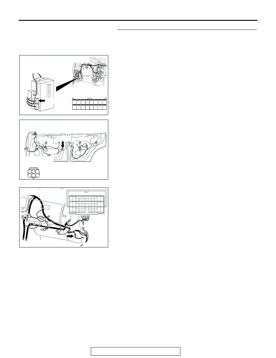
STEP 13. Check the wiring harness between front 
passenger's door lock actuator switch connector H-24 
(terminal 2) and ETACS-ECU connector D-223 (terminal 
46).

NOTE: Also check intermediate connector D-15 for loose, cor-
roded, or damaged terminals, or terminals pushed back in the 
connector. If intermediate connector D-15 is damaged, Repair 
or replace the damaged component(s) as described in GROUP 
00E, Harness Connector Inspection 

P.00E-2

.

Q: Is the wiring harness between front passenger's door 

lock actuator switch connector H-24 (terminal 2) and 
ETACS-ECU connector D-223 (terminal 46) in good 
condition?
YES : 
Replace the ETACS-ECU. If the functions, which are 

described in "CIRCUIT OPERATION", work normally, 
the input signal from the front passenger's door lock 
actuator switch should be normal.

NO :  The wiring harness may be damaged or the 

connector(s) may have loose, corroded or damaged 
terminals, or terminals pushed back in the connector. 
Repair the wiring harness as necessary. If the 
functions, which are described in "CIRCUIT 
OPERATION", work normally, the input signal from 
the front passenger's door lock actuator switch should 
be normal.

AC204174

CONNECTOR : D-223

AC

D-223(B)

D-223(B)

HARNESS SIDE

42

43

50

51

45

46

53

54

52

44

48

5655

47

49

41

AC204181

CONNECTOR : H-24

AE

HARNESS SIDE

<PASSENGER'S SIDE>

H-24(B)

H-24(B)

1

3 2

4

6 5

AC204171

CONNECTOR : D-15

AB

10

9

31

30

20 21

7

6

28

17 18

8

19

29

4

3

25 26

14 15

1

23

12

2

13

24

5

16

27

11

22

32

INPUT SIGNAL PROCEDURES

TSB Revision

SIMPLIFIED WIRING SYSTEM (SWS)

54B-598

STEP 14. Check back door lock actuator switch connector 
I-05 for loose, corroded or damaged terminals, or terminals 
pushed back in the connector.
Q: Is back door lock actuator switch connector I-05 in good 

condition?
YES : 
Go to Step 15.
NO :  Repair or replace the damaged component(s). Refer 

to GROUP 00E, Harness Connector Inspection 

P.00E-2

. If the functions, which are described in 

"CIRCUIT OPERATION", work normally, the input 
signal from the back door lock actuator switch should 
be normal.

STEP 15. Check the back door lock actuator switch.
Disconnect back door lock actuator switch connector I-05. 
Then check continuity between the switch terminals.

Q: Is the back door lock actuator switch in good 

condition?
YES : 
Go to Step 16.
NO :  Replace the back door lock actuator switch. If the 

functions, which are described in "CIRCUIT 
OPERATION", work normally, the input signal from 
the back door lock actuator switch should be normal.

AC204182

CONNECTOR : I-05

AC

HARNESS SIDE

I-05(B)

I-05(B)

1

3 2

4

6 5

LEVER 
POSITION

TESTER 
CONNECTION

SPECIFIED 
CONDITION

UNLOCK

− 6

Less than 2 ohms

ACX02356

LOCK

UNLOCK

VIEW A

A

AC

LEVER

INPUT SIGNAL PROCEDURES

TSB Revision

SIMPLIFIED WIRING SYSTEM (SWS)

54B-599

STEP 16. Check the ground circuit to the back door lock 
actuator switch. Test at back door lock actuator switch 
connector I-05.
(1) Disconnect back door lock actuator switch connector I-05 

and measure the resistance available at the wiring harness 
side of the connector.

(2) Measure the resistance value between terminal 6 and 

ground.

• The resistance should equal 2 ohms or less.

Q: Is the measured resistance 2 ohms or less?

YES : Go to Step 18.
NO :  Go to Step 17.

STEP 17. Check the wiring harness between back door 
lock actuator switch connector I-05 (terminal 6) and 
ground.
Q: Is the wiring harness between back door lock actuator 

switch connector I-05 (terminal 6) and ground in good 
condition?
YES : 
No action is necessary and testing is complete.
NO :  The wiring harness may be damaged or the 

connector(s) may have loose, corroded or damaged 
terminals, or terminals pushed back in the connector. 
Repair the wiring harness as necessary. If the 
functions, which are described in "CIRCUIT 
OPERATION", work normally, the input signal from 
the back door lock actuator switch should be normal.

AC204182

CONNECTOR : I-05

AC

HARNESS SIDE

I-05(B)

I-05(B)

1

3 2

4

6 5

5

4

3

2

1

6

ACX01605 AG

CONNECTOR I-05
(HARNESS SIDE)

AC204182

CONNECTOR : I-05

AC

HARNESS SIDE

I-05(B)

I-05(B)

1

3 2

4

6 5

INPUT SIGNAL PROCEDURES

TSB Revision

SIMPLIFIED WIRING SYSTEM (SWS)

54B-600

STEP 18. Check ETACS-ECU connector D-223 for loose, 
corroded or damaged terminals, or terminals pushed back 
in the connector.
Q: Is ETACS-ECU connector D-223 in good condition?

YES : Go to Step 19.
NO :  Repair or replace the damaged component(s). Refer 

to GROUP 00E, Harness Connector Inspection 

P.00E-2

. If the functions, which are described in 

"CIRCUIT OPERATION", work normally, the input 
signal from the back door lock actuator switch should 
be normal.

STEP 19. Check the wiring harness between back door 
lock actuator switch connector I-05 (terminal 4) and 
ETACS-ECU connector D-223 (terminal 47).

AC204174

CONNECTOR : D-223

AC

D-223(B)

D-223(B)

HARNESS SIDE

42

43

50

51

45

46

53

54

52

44

48

5655

47

49

41

AC204174

CONNECTOR : D-223

AC

D-223(B)

D-223(B)

HARNESS SIDE

42

43

50

51

45

46

53

54

52

44

48

5655

47

49

41

AC204182

CONNECTOR : I-05

AC

HARNESS SIDE

I-05(B)

I-05(B)

1

3 2

4

6 5


Content   ..  833  834  835  836   ..