Mitsubishi Montero (2004+). Manual - part 717
SYMPTOM PROCEDURES
TSB Revision
SIMPLIFIED WIRING SYSTEM (SWS)
54B-125
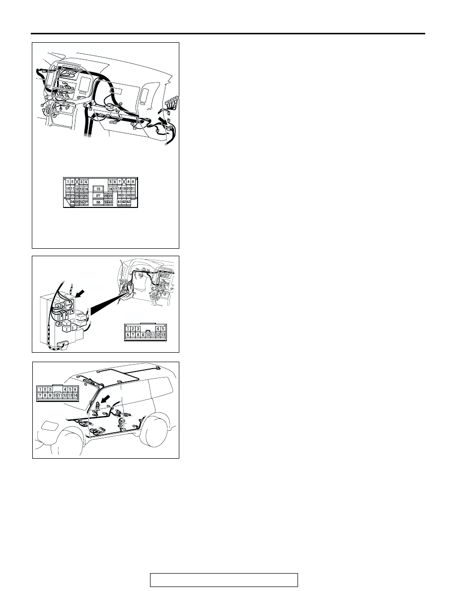
NOTE: Also check junction block connector D-209 and inter-
mediate connector D-111 and F-23 for loose, corroded, or dam-
aged terminals, or terminals pushed back in the connector. If
junction block connector D-209 or intermediate connector
D-111 or F-23 are damaged, repair or replace the damaged
component(s) as described in GROUP 00E, Harness Connec-
tor Inspection
.
Q: Is the harness wiring from ETACS-ECU connector D-222
(terminal 4) to rear passenger's door lock actuator (RH)
connector H-21 (terminal 3) in good condition?
YES : Go to Step 21.
NO : The harness wiring may be damaged or the
connectors may have loose, corroded or damaged
terminals, or terminals pushed back in the connector.
Repair the harness wiring as necessary. After repairs
have been made, verify that all the doors can now be
locked and unlocked normally.
AC203860AC
D-111
CONNECTOR: D-111
D-111
AC203850
CONNECTOR: D-209
AE
D-209
D-209
JUNCTION BLOCK
(FRONT VIEW)
AC204484
AC
CONNECTOR: F-23
F-23
F-23