Mitsubishi Montero (2004+). Manual - part 665


  Index      Mitsubishi     Mitsubishi Montero - service repair manual 2004 year


Search            


Content   ..  663  664  665  666   ..


Mitsubishi Montero (2004+). Manual - part 665


HEATER UNIT

TSB Revision

AUTOMATIC AIR CONDITIONING

55B-149

DISASSEMBLY AND REASSEMBLY
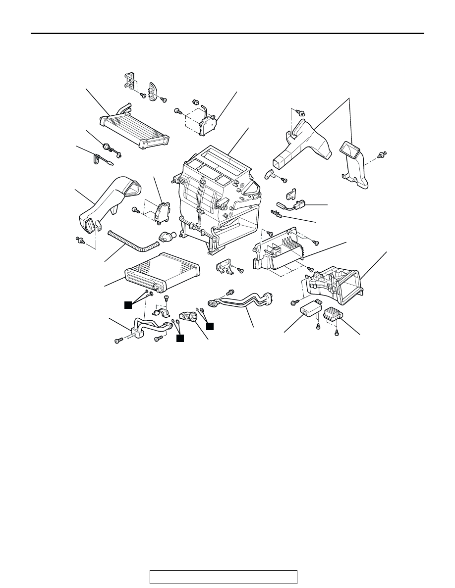
M1554009200083

ASSEMBLY SERVICE POINT

.

>>A<< HEATER WATER TEMPERATURE SENSOR/HEATER 
WATER TEMPERATURE SENSOR CLIP INSTALLATION
Insert the heater water temperature sensor into the mounting 
hole on the heater unit, and secure the sensor with the clip.

AC205222

1

2

3

4

5

6

7

8

9

10

11

12

13

14

15

16

17

18

19

N

N

N

AB

DISASSEMBLY STEPS

1.

FOOT DUCT A

2.

FOOT DUCT C

3.

AIR THERMO SENSOR CLIP

4.

AIR THERMO SENSOR

>>A<<

5.

HEATER WATER TEMPERATURE 
SENSOR CLIP

>>A<<

6.

HEATER WATER TEMPERATURE 
SENSOR

7.

MODE SELECTION DAMPER 
CONTROL MOTOR

8.

AIR MIXING DAMPER CONTROL 
MOTOR

9.

ASPIRATOR HOSE

10. HEATER BLOWER CONTROLLER 

UNIT

11. REAR COOLER CONTROL UNIT 

OR REAR A/C CONTROL UNIT

12. JOINT DUCT
13. AIR DUCT SUBASSEMBLY
14. HEATER CORE
15. FRONT PIPE ASSEMBLY
16. EXPANSION VALVE
17. PIPE
18. EVAPORATOR
19. CASE

DISASSEMBLY STEPS 

HEATER BLOWER CONTROLLER UNIT

TSB Revision

AUTOMATIC AIR CONDITIONING

55B-150

HEATER BLOWER CONTROLLER UNIT

REMOVAL AND INSTALLATION

M1554009400010

INSPECTION

M1554009500017

BLOWER LINER CONTROLLER

When the connector is connected and the ignition switch is 
turned ON, the voltage at terminal 2 should be as follows:

AC101450

BLOWER LINER 
CONTROLLER

AB

BLOWER SWITCH POSITION

VOLTAGE AT TERMINAL 
No. 2 V

LOW SPEED

4.0

MEDIUM SPEED

7.9

HIGH SPEED

13.7

ACX00825AC

DAMPER CONTROL MOTOR ASSEMBLY

TSB Revision

AUTOMATIC AIR CONDITIONING

55B-151

DAMPER CONTROL MOTOR ASSEMBLY

REMOVAL AND INSTALLATION

M1554001600032

INSPECTION

M1554001700051

.

AIR MIX DAMPER CONTROL MOTOR CHECK

CAUTION

Do not apply battery voltage when the damper is in the 
MAX COOL or MAX HOT position.
Check the air mix damper control motor by the following proce-
dures.

ACX01447

1

2

REMOVAL STEPS

UNDER COVER (REFER TO 
GROUP 52A, INSTRUMENT 
PANEL 

P.52A-3

.)

1.

AIR MIX DAMPER MOTOR

2.

AIR OUTLET CHANGEOVER 
DAMPER MOTOR

REMOVAL STEPS (Continued)

ACX01456

MAX HOT
POSITION

MAX COOL
POSITION

AB

DAMPER CONTROL MOTOR ASSEMBLY

TSB Revision

AUTOMATIC AIR CONDITIONING

55B-152

.

POTENTIOMETER CHECK
While checking the air mix damper control motor, measure the 
resistances between terminals numbers 3 and 5 as well as 
numbers 3 and 7. At this time, the resistances should change 
gradually within the standard value.

Standard value: 1.2 

 4.8 k

.

MODE SELECTION DAMPER CONTROL MOTOR CHECK

CAUTION

Do not apply battery voltage when the damper is in the 
FACE or DEF position.
Check the mode selection damper control motor by the follow-
ing procedures.

.

POTENTIOMETER CHECK
While checking the mode selection damper control motor, mea-
sure the resistances between terminal numbers 3 and 5 as well 
as terminal numbers 3 and 7. At this time, the resistances 
should change gradually within the standard value.

Standard value: 0.96 

 5.76 k

LEVER 
POSITION

BATTERY 
CONNECTION

LEVER 
OPERATION

At the MAX 
COOL position

• Connect terminal 1 

to the positive 
battery terminal

• Connect terminal 2 

to the negative 
battery terminal

The lever moves 
from the MAX 
COOL position to 
the outside position

At the MAX 
HOT position

• Connect terminal 2 

to the positive 
battery terminal

• Connect terminal 1 

to the negative 
battery terminal

The lever moves 
from the MAX HOT 
position to the 
inside position

LEVER 
POSITION

BATTERY 
CONNECTION

LEVER 
OPERATION

At the DEF 
position

• Connect terminal 1 

to the positive 
battery terminal

• Connect terminal 2 

to the negative 
battery terminal

The lever moves 
from the DEF 
position to the 
outside position

At the FACE 
position

• Connect terminal 2 

to the positive 
battery terminal

• Connect terminal 1 

to the negative 
battery terminal

The lever moves 
from the FACE 
position to the 
inside position

ACX01457

FACE POSITION

DEF POSITION

AB


Content   ..  663  664  665  666   ..