Mitsubishi Montero (2004+). Manual - part 661


  Index      Mitsubishi     Mitsubishi Montero - service repair manual 2004 year


Search            


Content   ..  659  660  661  662   ..


Mitsubishi Montero (2004+). Manual - part 661


AUTO A/C DIAGNOSIS

TSB Revision

AUTOMATIC AIR CONDITIONING

55B-133

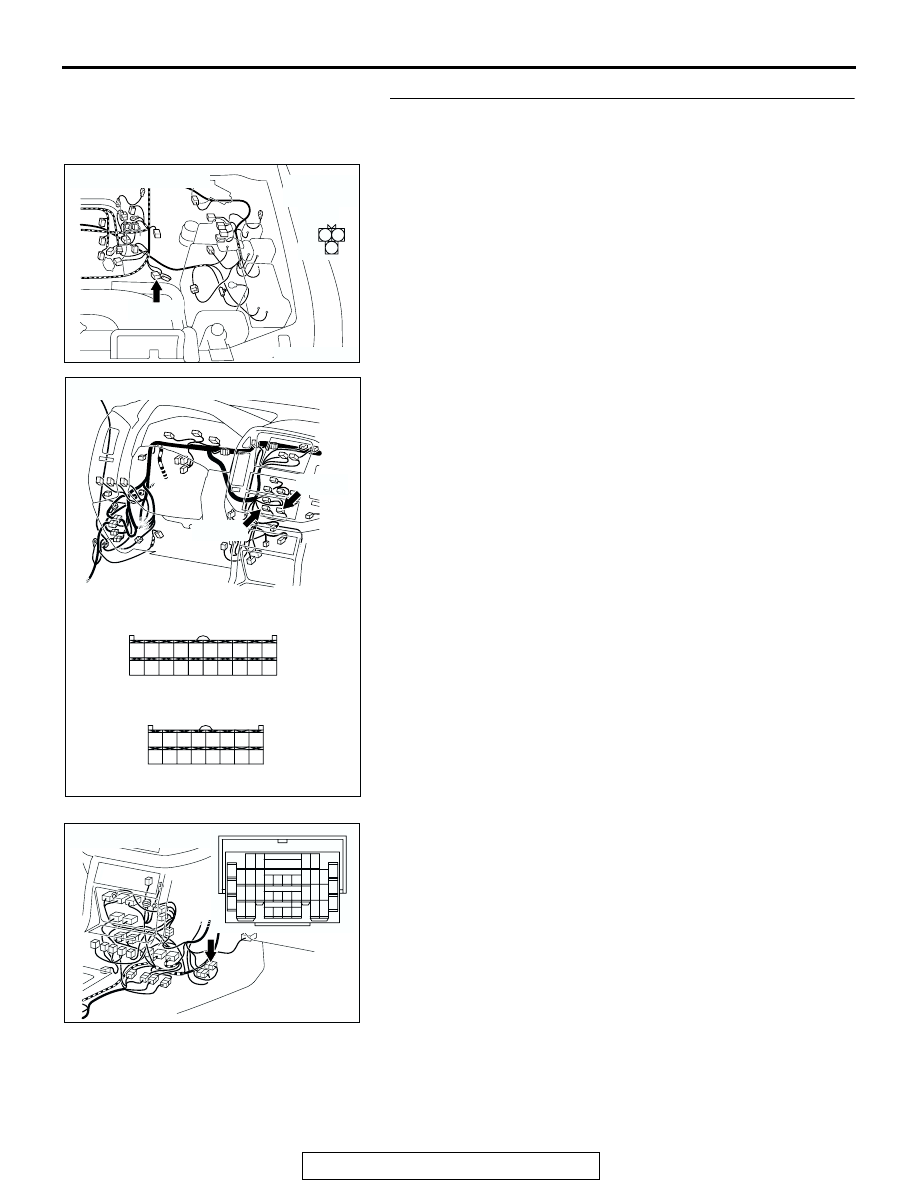
STEP 2. Check the wiring harness between A/C-ECU 
connector D-23 (terminal 9), D-24 (terminal 29) and A/C 
compressor connector B-30 (terminal 1, 2).

NOTE: Also check intermediate connector E-111. If intermedi-
ate connector E-111 is damaged, repair or replace the connec-
tor as described in GROUP 00E, Harness Connector 
Inspection 

P.00E-2

.

Q: Is the wiring harness between A/C-ECU connector D-23 

(terminal 9), D-24 (terminal 29) and A/C compressor 
connector B-30 (terminal 1, 2) in good condition?
YES : 
Go to Step 3.
NO :  Repair the wiring harness. Check that the air 

conditioning works normally.

AC204169

CONNECTOR : B-30

AE

B-30(B)

B-30(B)

2

3

1

HARNESS 
SIDE

AC204188

CONNECTORS : D-23, D-24

D-24(B)

D-24(B)

D-23(B)

D-23(B)

HARNESS SIDE

HARNESS SIDE

BH

22

30 29

21

23

31

25

26

33

34

32

24

28

3635

27

1

3

4

2

12

1413

11

6

7

8

10 9

18

19

20

16

17

5

15

AC204176

CONNECTOR : E-111

BF

15

4

14

37

36

26 27

12

11

35

34

23 24

3

13

25

9

2

8

32

20 21

6

5

17

29

30

18

1

7

19

31

10

22

33

16

28

38

AUTO A/C DIAGNOSIS

TSB Revision

AUTOMATIC AIR CONDITIONING

55B-134

STEP 3. Replace the lock sensor.
Q: Does the air conditioning work normally?

YES : No action is necessary and testing is complete.
NO :  Replace the A/C-ECU (Refer to 

P.55B-142

). Check 

that the air conditioning works normally.

DATA LIST REFERENCE TABLE

M1554005100169

MUT-III SCAN 
TOOL DISPLAY

ITEM 
NO.

INSPECTION ITEM INSPECTION REQUIREMENT

NORMAL VALUE

A/M DAMPER

31

Air mixing damper 
control motor 
potentiometer

Ignition switch: ON Damper 

position

Opening degree (%)

MAX. HOT

Approx. 100

MAX. COOL

Approx. 0

OUTSIDE TEMP 13

Outside air 
temperature sensor

Ignition switch: ON

Outside air 
temperature and 
temperature 
displayed on scan 
tool are identical.

EVAP TEMP

21

A/C sensor

Ignition switch: ON

The temperature of 
the air, which flows 
through the 
evaporator, and 
temperature 
displayed on scan 
tool are identical.

AIR OUT POS

32

Mode selection 
damper control 
motor potentiometer

Ignition switch: ON Damper 

position

Opening degree (%)

FACE

Approx. 0

FOOT

Approx. 50

FOOT/DEF.

Approx. 75

DEF.

Approx. 100

PHOTO SNSR

25

Photo sensor

Ignition switch: ON

Amount of incident 
light is proportional 
to voltage displayed 
on scan tool.

INSIDE TEMP

11

Inside air 
temperature sensor

Ignition switch: ON

Inside air 
temperature and 
temperature 
displayed on scan 
tool are identical.

HEATER TEMP

15

heater water 
temperature sensor

Ignition switch: ON

ON when heater 
core wall 
temperature is 30

°C 

(86

°F) or higher.

AUTO A/C DIAGNOSIS

TSB Revision

AUTOMATIC AIR CONDITIONING

55B-135

ACTUATOR TEST REFERENCE

M1554005200155

CHECK AT ECU TERMINAL

M1554005400171

MUT-III SCAN TOOL 
DISPLAY

ITEM 
NO.

INSPECTION ITEM

DRIVE CONTENT

A/M 0%

05

Air mix damper motor

Opening degree: approx. 0%

A/M 100%

07

Opening degree: approx. 100%

A/M 50%

06

Opening degree: approx. 50%

CLUTCH OFF

11

A/C compressor

OFF

CLUTCH ON

12

ON

DEF

10

Air outlet changeover damper motor DEF

FACE

08

FACE

FAN HI

04

Blower motor

HI

FAN LO

02

LO

FAN ME

03

ME

FAN OFF

01

OFF

FOOT

09

Air outlet changeover damper motor FOOT

FRESH

13

Inlet/outlet air changeover damper 
motor

FRESH

RECIRC

14

RECIRCULATION

1

2 3 4 5 6

7 8

9 10

11 12 13 14 15 16 17 18 19 20

32 33 34

29

30 31

21 22 23 24 25 26 27 28

35 36

AC002694

TERMINAL 
NO.

INSPECTION ITEM

INSPECTION CONDITION

NORMAL 
CONDITION

1

Air mixing damper control 
motor

When the air mix damper is moved to the 
MAX. COOL position. 

10 V

When the air mix damper is moved to the 
MAX. HOT position. 

0.5 V

2

Mode selection damper control 
motor (FACE)

When the damper is moved to the FACE 
position. 

10 V

When the damper is moved to the DEF 
position. 

0.5 V

3

Inside/outside air changeover 
damper motor (inside air)

When the damper flap is moving to the 
inside air recirculation position.

0.5 V

When the damper flap is moving to the 
outside air induction position.

10 V (when the 
motor is stopped)

4

Inside/outside air changeover 
damper motor (FRESH)

When the damper flap is moving to the 
inside air recirculation position.

0 V (when the 
motor is stopped)

When the damper flap is moving to the 
outside air induction position.

0.5 V

AUTO A/C DIAGNOSIS

TSB Revision

AUTOMATIC AIR CONDITIONING

55B-136

5

Request signal for turning the 
A/C compressor on

Dual pressure switch: OFF

System voltage

Dual pressure switch: ON

0 V

6

RV meter communication line

Ignition switch: ON

Hi: 4 

− 5 V

Lo: 0 

− 1 V

7

PCM communication line

When the A/C is off.

0 V

When the A/C (compressor) is operating System voltage

8

-

-

-

9

Lock sensor input

When the compressor is operating

− 0.75 V (pulse 

signal)

10

Heater blower controller unit 
output

When the blower is operating

− 3.5 V 

(alternative 
effective value)

11

Air mixing damper control 
motor

When the air mix damper is moved to the 
MAX. COOL position. 

0.5 V

When the air mix damper is moved to the 
MAX. HOT position. 

10 V

12

Air outlet changeover damper 
motor (DEF)

When the damper is moved to the FACE 
position. 

0.5 V

When the damper is moved to the DEF 
position. 

10 V

13

-

-

-

14

Blower relay

When the blower is stopped

System voltage

When the blower is operating

0 V

15

Rear defogger

Rear defogger: OFF

System voltage

Rear defogger: ON

0 V

16

RV meter communication line

Ignition switch: ON

Hi: 4 

− 5 V

Lo: 0 

− 1 V

17

RV meter communication line

Ignition switch: ON

Hi: 4 

− 5 V

Lo: 0 

− 1 V

18

RV meter communication line 
shield

At all times

0 V

19

Diagnosis code set

Ignition switch: ON

⇔ Battery 

positive voltage

20

A/C compressor relay input

When the A/C is off.

0 V

When the A/C (compressor) is operating System voltage

21

Potentiometer power supply

At all times

5 V

22

Outside air temperature sensor 
input

When sensor section temperature is 
25

°C (77°F) [4 kΩ]

1.9 V

23

Heater water temperature 
sensor input

When sensor section temperature is 
25

°C (77°F) [4 kΩ]

2.8 V

24

Air mixing damper control 
motor potentiometer input

When the damper door has moved to the 
MAX. HOT position. 

0.7 

− 1.3 V

25

ILL power supply

Lighting switch: ON

System voltage

TERMINAL 
NO.

INSPECTION ITEM

INSPECTION CONDITION

NORMAL 
CONDITION


Content   ..  659  660  661  662   ..