Mitsubishi Montero (2004+). Manual - part 658


  Index      Mitsubishi     Mitsubishi Montero - service repair manual 2004 year


Search            


Content   ..  656  657  658  659   ..


Mitsubishi Montero (2004+). Manual - part 658


AUTO A/C DIAGNOSIS

TSB Revision

AUTOMATIC AIR CONDITIONING

55B-121

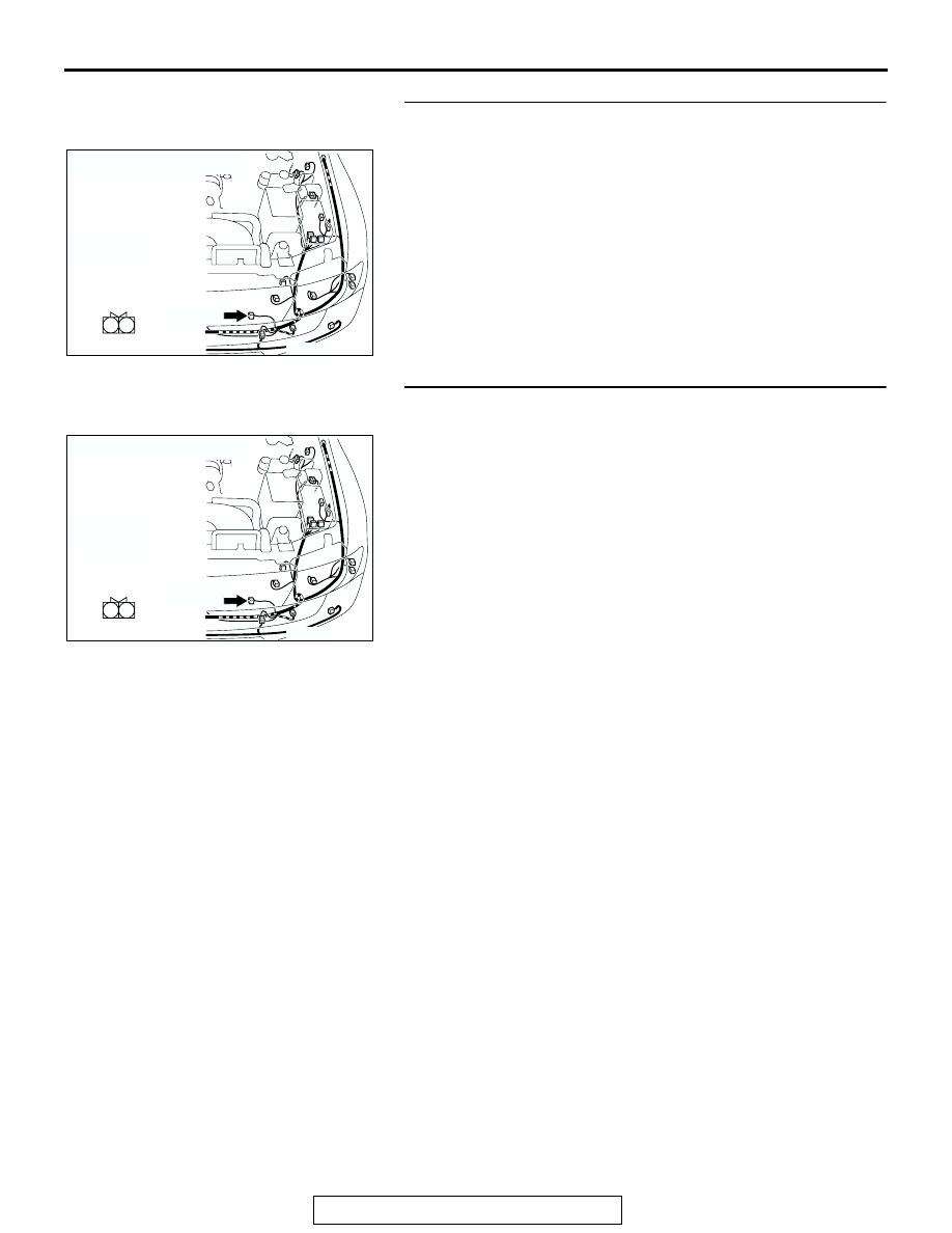
STEP 16. Check condenser fan motor connector A-26 for 
damage.
Q: Is condenser fan motor connector A-26 in good 

condition?
YES : 
Go to Step 17.
NO :  Repair or replace the connector. Refer to GROUP 

00E, Harness Connector Inspection 

P.00E-2

. The 

blower motor should operate normally.

STEP 17. Check the wiring harness between condenser fan 
motor connector A-26 (terminal 2) and ground.

Q: Is the wiring harness between condenser fan motor 

connector A-26 (terminal 2) and ground in good 
condition?
YES : 
No action to be taken.
NO :  Repair the wiring harness. The blower motor should 

operate normally.

AC204167

CONNECTOR : A-26

AX

A-26(B)

A-26(B)

1

2

HARNESS SIDE

AC204167

CONNECTOR : A-26

AX

A-26(B)

A-26(B)

1

2

HARNESS SIDE

AUTO A/C DIAGNOSIS

TSB Revision

AUTOMATIC AIR CONDITIONING

55B-122

INSPECTION PROCEDURE 10: Malfunction of the A/C-ECU Power Supply System.

FUSIBLE
LINK

1

IGNITION
SWITCH (ACC)

IGNITION
SWITCH (IG2)

JUNCTION 
BLOCK

DEDICATED
FUSE

POWER SOURCE

RELAY
BOX

JOINT 
CONNECTOR (6)

JOINT 
CONNECTOR (7)

JOINT 
CONNECTOR (8)

A/C-ECU

A/C Power Supply Circuit

AUTO A/C DIAGNOSIS

TSB Revision

AUTOMATIC AIR CONDITIONING

55B-123

.

TECHNICAL DESCRIPTION (COMMENT)
The A/C-ECU power system may be defective if the 
air conditioning, defogger, and outside/inside air 
changeover damper motor all do not operate nor-
mally.

.

TROUBLESHOOTING HINTS

• Malformation of the A/C-ECU

• Damaged harness wires or connectors

DIAGNOSIS

Required Special Tool:

• MB991223: Test Harness Set

STEP 1. Measure the voltage at A/C-ECU connector D-24. 

(1) Disconnect A/C-ECU connector D-24 and measure the 

voltage at the harness side.

(2) Turn the ignition switch to the "ON" position.

(3) Measure the voltage between terminal 26 and ground.

• The measured value should be approximately 12 volts 

(battery positive voltage).

Q: Does the measured voltage correspond with this range?

YES :  Go to Step 4.
NO :   Go to Step 2.

AC204170

CONNECTORS : D-01, D-02, D-24, D-28, 
D-29, D-30

DR

D-24(B)

D-30

D-01

D-28

D-29

D-02

AC204173 BS

D-210

D-221

D-208

CONNECTORS : D-208, D-210, D-221

AC204170

CONNECTOR : D-24

D-24(B)

D-24(B)

CQ

22

23

30

31

25

26

33

34

32

24

28

3635

27

29

21

HARNESS 
SIDE

AC204738 DH

HARNESS SIDE : D-24

22

23

30

31

25

26

33

34

32

24

28

3635

27

29

21

AUTO A/C DIAGNOSIS

TSB Revision

AUTOMATIC AIR CONDITIONING

55B-124

STEP 2. Check A/C-ECU connector D-24 for damage.
Q:  Is A/C-ECU connector D-24 in good condition?

YES : Go to Step 3.
NO :  Repair or replace the connector. Refer to GROUP 

00E, Harness Connector Inspection 

P.00E-2

. Check 

that the air conditioning works normally.

STEP 3. Check the wiring harness between A/C-ECU 
connector D-24 (terminal 26) and the ignition switch (IG2).

AC204170

CONNECTOR : D-24

D-24(B)

D-24(B)

CQ

22

23

30

31

25

26

33

34

32

24

28

3635

27

29

21

HARNESS 
SIDE

AC204188

CONNECTOR : D-01, D-24

D-24(B)

D-24(B)

CM

22

23

30

31

25

26

33

34

32

24

28

3635

27

29

21

HARNESS SIDE

9 10

8

6 7

31 32

30

29

18 19 20 21

5

4

2

1

3

27

26

24

23

25

12 13 14 15 16 17

28

11
22
33

D-01

HARNESS SIDE

D-01


Content   ..  656  657  658  659   ..