Mitsubishi Montero (2004+). Manual - part 654


  Index      Mitsubishi     Mitsubishi Montero - service repair manual 2004 year


Search            


Content   ..  652  653  654  655   ..


Mitsubishi Montero (2004+). Manual - part 654


AUTO A/C DIAGNOSIS

TSB Revision

AUTOMATIC AIR CONDITIONING

55B-105

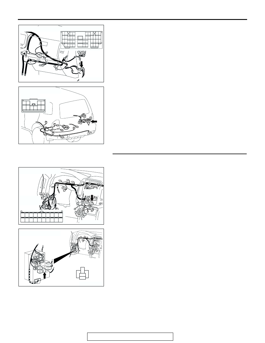
NOTE: Also check junction block connector D-217, intermedi-
ate connectors D-111 and G-10. If junction block connector 
D-217, intermediate connector D-111 or G-10 is damaged, 
repair or replace the connector as described in GROUP 00E, 
Harness Connector Inspection 

P.00E-2

.

Q: Is the wiring harness between defogger relay connector 

D-216 (terminal 5) and defogger connector I-03 (terminal 
1) in good condition?
YES : 
Go to Step 12.
NO :  Repair or replace the wiring harness. Refer to 

GROUP 00E, Harness Connector Inspection 

P.00E-2

. Check that the defogger system works 

normally.

STEP 12. Check defogger relay connector D-216 and 
A/C-ECU connector D-23 for damage.

Q: Are defogger relay connector D-216 and A/C-ECU 

connector D-23 in good condition?
YES : 
Go to Step 13.
NO :  Repair or replace the connector. Refer to GROUP 

00E, Harness Connector Inspection 

P.00E-2

. Check 

that the defogger system works normally.

AC204171

CONNECTOR : D-111

AQ

9

8

6 7

5

3 4

20

32

21

33

43

17 18

30

41

16

29

28

39 40

13

25

12

24

35 36

14

26

37

15

27

38

19

31

42

1

10

22

2

11

23

34

AC204179

CONNECTOR : G-10

AD

4

10

8

7

3

9

5

1

6

2

AC204170

CONNECTOR : D-23

D-23(B)

D-23(B)

CP

HARNESS 
SIDE

1

3

4

2

12

1413

11

6

7

8

10 9

18

19

20

16

17

5

15

AC204173

CONNECTOR : D-216

BD

JUNCTION BLOCK 
SIDE

1

2

5

4

3

AUTO A/C DIAGNOSIS

TSB Revision

AUTOMATIC AIR CONDITIONING

55B-106

STEP 13. Check the wiring harness between defogger 
relay connector D-216 (terminal 3) and A/C-ECU connector 
D-23 (terminal 15).

NOTE: Also check junction block connector D-209. If junction 
block connector D-209 is damaged, repair or replace the con-
nector as described in GROUP 00E, Harness Connector 
Inspection 

P.00E-2

.

Q: Is the wiring harness between defogger relay connector 

D-216 (terminal 3) and A/C-ECU connector D-23 
(terminal 15) in good condition?
YES : 
Go to Step 18.
NO :  Repair or replace the wiring harness. Refer to 

GROUP 00E, Harness Connector Inspection 

P.00E-2

. Check that the defogger system works 

normally.

AC204170

CONNECTOR : D-23

D-23(B)

D-23(B)

CP

HARNESS 
SIDE

1

3

4

2

12

1413

11

6

7

8

10 9

18

19

20

16

17

5

15

AC204191

JUNCTION BLOCK
(FRONT VIEW)

CONNECTORS : D-209, D-216

D-209

HARNESS SIDE

D-216

RELAY SIDE

AX

D-209

D-216

1

2

5

4

3

1

2

6

7

9

3

4

11

12

10

5

13

8

AUTO A/C DIAGNOSIS

TSB Revision

AUTOMATIC AIR CONDITIONING

55B-107

STEP 14. Measure at defogger connector I-01 to check the 
ground circuit to the defogger connector.
(1) Disconnect defogger connector I-01, and measure at the 

wiring harness side.

(2) Measure the resistance value between terminal 1 and 

ground.

• 2 ohms or less

Q: Does the measured resistance value correspond with 

this range?
YES : 
 Go to Step 17.
NO :   Go to Step 15.

STEP 15. Check defogger connector I-01 for damage.

Q: Is defogger connector I-01 in good condition?

YES : Go to Step 16.
NO :  Repair or replace the connector. Refer to GROUP 

00E, Harness Connector Inspection 

P.00E-2

. Check 

that the defogger system works normally.

STEP 16. Check the wiring harness between defogger 
connector I-01 (terminal 1) and ground.

Q: Is the wiring harness between defogger connector I-01 

(terminal 1) and ground in good condition?
YES : 
Check that the defogger system works normally.
NO :  Repair or replace the wiring harness. Refer to 

GROUP 00E, Harness Connector Inspection 

P.00E-2

. Check that the defogger system works 

normally.

AC204182

CONNECTOR : I-01

AJ

I-01(B)

I-01(B)

1

HARNESS 
SIDE

AC201095

1

AC

HARNESS SIDE : I-01

AC204182

CONNECTOR : I-01

AJ

I-01(B)

I-01(B)

1

HARNESS 
SIDE

AC204182

CONNECTOR : I-01

AJ

I-01(B)

I-01(B)

1

HARNESS 
SIDE

AUTO A/C DIAGNOSIS

TSB Revision

AUTOMATIC AIR CONDITIONING

55B-108

STEP 17. Check the defogger.

(1) Run engine at 2,000 r/min. Check heater element with 

battery at full.

(2) Turn "ON "rear window defogger switch. Measure heater 

element voltage with circuit tester at rear window glass 
center A. Condition is good if it indicates about six volts.

(3) If 12 volts is indicated at A, there is a break in the negative 

terminals from A. Move test bar slowly to negative terminal 
to detect where voltage changes suddenly (0 volt).

(4) If 0 volt is indicated at A, there is a break in the positive 

terminals from A. Defect where the voltage changes 
suddenly (12 volts, battery positive voltage) in the same 
method described above.

Q: Does the defogger work normally? 

YES : Check that the defogger system works normally.
NO :  Replace the back door glass. Refer to GROUP 42, 

Window glass 

− Back door window glass 

P.42-18

.

STEP 18. Check the flexible flat cable (FFC).

(1) The FCC is connected to the automatic air conditioning 

control panel assembly. Check that the FCC connection is 
contaminated with foreign material or loose (Refer to 

P.55B-142

).

(2) There should be continuity across the FFC terminals.
Q: Is the FFC normal?

YES : Go to Step 19.
NO :  Repair the FFC (Refer to 

P.55B-142

). Check that the 

defogger system works normally.

ACX00813

NORMAL CHARACTERSTIC CURVE

ABNORMAL CHARACTERSTIC CURVE

VOLTAGE

A (CENTER POINT)

APPROXIMATELY
                         6 V

NEGATIVE
TERMINAL

PRINTED 
HEATER
LINE

POSITIVE
TERMINAL

NEGATIVE
TERMINAL

PRINTED 
HEATER
LINE

POSITIVE
TERMINAL

OPENCIRCUIT 
POINT

VOLTAGE

AC

AC205264AB


Content   ..  652  653  654  655   ..