Mitsubishi Montero (2004+). Manual - part 629


  Index      Mitsubishi     Mitsubishi Montero - service repair manual 2004 year


Search            


Content   ..  627  628  629  630   ..


Mitsubishi Montero (2004+). Manual - part 629


AUTO A/C DIAGNOSIS

TSB Revision

AUTOMATIC AIR CONDITIONING

55B-5

CAUTION

To prevent damage to scan tool MB991958, always turn the 
ignition switch to the "LOCK" (OFF) position before con-
necting or disconnecting scan tool MB991958.
1. Ensure that the ignition switch is at the "LOCK" (OFF) 

position.

2. Start up the personal computer.
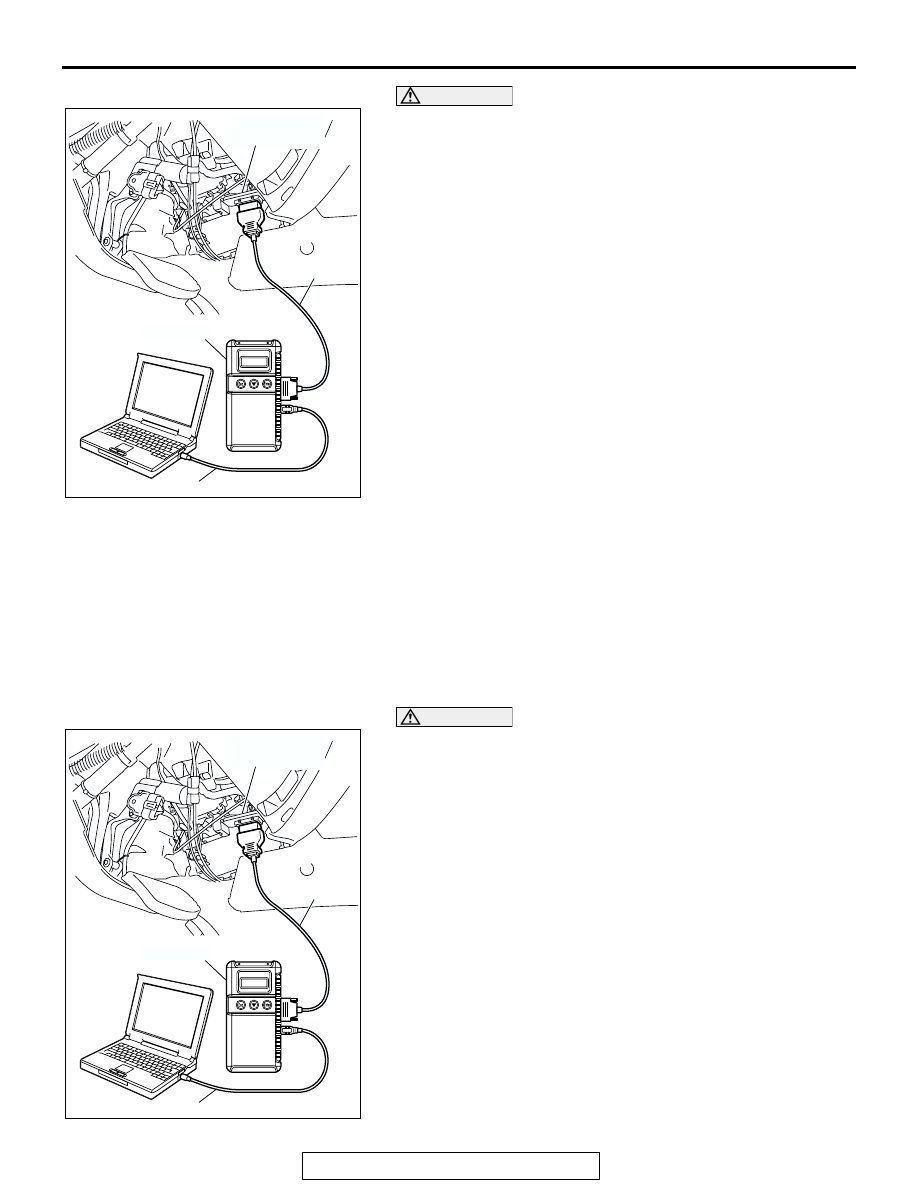
3. Connect special tool MB991827 to special tool MB991824 

and the personal computer.

4. Connect special tool MB991911 to special tool MB991824
5. Connect special tool MB991911 to the data link connector.
6. Turn the power switch of special tool MB991824 to the "ON" 

position.
NOTE: When the special tool MB991824 is energized, the 
special tool MB991824 indicator light will be illuminated in a 
green color.

7. Start the MUT-III system on the personal computer.
NOTE: Disconnecting scan tool special tool MB991958 is the 
reverse of the connecting sequence, making sure that the igni-
tion switch is at the "LOCK" (OFF) position.

HOW TO READ AND ERASE DIAGNOSTIC 
TROUBLE CODES

Required Special Tool:

•  MB991958: Scan Tool (MUT-III Sub Assembly)

• MB991824: Vehicle Communication Interface (V.C.I.)

• MB991827: MUT-III USB Cable

• MB991911: MUT-III Main Harness B (Vehicles without 

CAN communication system)

CAUTION

To prevent damage to scan tool MB991958, always turn the 
ignition switch to the "LOCK" (OFF) position before con-
necting or disconnecting scan tool MB991958.
NOTE: If the battery voltage is low, diagnostic trouble codes will 
not be set. Check the battery if scan tool MB991958 does not 
display.
1. Connect scan tool MB991958 to the data link connector.
2. Turn the ignition switch to the "ON" position.
3. Select "Interactive Diagnosis" from the start-up screen.
4. Select "System Select."
5. Choose "AUTO A/C" from the "BODY" tab.
6. Select "MITSUBISHI."
7. Select "Diagnostic Trouble Code."
8. If a DTC is set, it is shown.
9. Choose "Erase DTC" to erase the DTC.

AC307591 AB

MB991911

DATA LINK

CONNECTOR

MB991824

MB991827

AC307591 AB

MB991911

DATA LINK

CONNECTOR

MB991824

MB991827

AUTO A/C DIAGNOSIS

TSB Revision

AUTOMATIC AIR CONDITIONING

55B-6

HOW TO READ DATA LIST

Required Special Tool:

•  MB991958: Scan Tool (MUT-III Sub Assembly)

• MB991824: Vehicle Communication Interface (V.C.I.)

• MB991827: MUT-III USB Cable

• MB991911: MUT-III Main Harness B (Vehicles without 

CAN communication system)

CAUTION

To prevent damage to scan tool MB991958, always turn the 
ignition switch to the "LOCK" (OFF) position before con-
necting or disconnecting scan tool MB991958.
1. Connect scan tool MB991958 to the data link connector.
2. Turn the ignition switch to the "ON" position.
3. Select "Interactive Diagnosis" from the start-up screen.
4. Select "System Select."
5. Choose "AUTO A/C" from the "BODY" tab.
6. Select "MITSUBISHI."
7. Select "Data List."
8. Choose an appropriate item and select the "OK" button.

HOW TO PERFORM ACTUATOR TEST

Required Special Tool:

•  MB991958: Scan Tool (MUT-III Sub Assembly)

• MB991824: Vehicle Communication Interface (V.C.I.)

• MB991827: MUT-III USB Cable

• MB991911: MUT-III Main Harness B (Vehicles without 

CAN communication system)

AC307591 AB

MB991911

DATA LINK

CONNECTOR

MB991824

MB991827

AUTO A/C DIAGNOSIS

TSB Revision

AUTOMATIC AIR CONDITIONING

55B-7

CAUTION

To prevent damage to scan tool MB991958, always turn the 
ignition switch to the "LOCK" (OFF) position before con-
necting or disconnecting scan tool MB991958.
1. Connect scan tool MB991958 to the data link connector.
2. Turn the ignition switch to the "ON" position.
3. Select "Interactive Diagnosis" from the start-up screen.
4. Select "System Select."
5. Choose "AUTO A/C" from the "BODY" tab.
6. Select "MITSUBISHI."
7. Choose "Actuator Test" from "AUTO A/C" screen.
8. Choose an appropriate item and select the "OK" button.

DIAGNOSTIC TROUBLE CODE CHART

M1554004900043

SYMPTOM CHART

M1554005000225

AC307591 AB

MB991911

DATA LINK

CONNECTOR

MB991824

MB991827

DIAGNOSTIC 
TROUBLE CODE NO.

DIAGNOSTIC ITEM

REFERENCE 
PAGE

11

Inside air temperature sensor system (open circuit)

P.55B-8

12

Inside air temperature sensor system (short circuit)

P.55B-8

13

Outside air temperature sensor system (open circuit)

P.55B-9

14

Outside air temperature sensor system (short circuit)

P.55B-9

15

Heater water temperature sensor system (open circuit)

P.55B-13

16

Heater water temperature sensor system (short circuit)

P.55B-13

21

Air thermo sensor system (open circuit)

P.55B-17

22

Air thermo sensor system (short circuit)

P.55B-17

31

Potentiometer system of air mixing damper control motor assembly

P.55B-20

32

Potentiometer system of air outlet changeover damper control 
motor assembly

P.55B-24

SYMPTOM

INSPECTION 
PROCEDURE NO.

REFERENCE 
PAGE

Communication with scan tool is not possible.

1

P.55B-28

Air conditioning does not operate.

2

P.55B-34

A/C outlet air temperature cannot be set.

3

P.55B-54

Blower does not operate.

4

P.55B-63

Blower air amount cannot be changed.

5

P.55B-80

Air outlets cannot be changed.

6

P.55B-84

AUTO A/C DIAGNOSIS

TSB Revision

AUTOMATIC AIR CONDITIONING

55B-8

DIAGNOSTIC TROUBLE CODE PROCEDURES

DTC 11, 12: Inside Air Temperature Sensor System

.

DTC SET CONDITION
DTC 11 or 12 is displayed when the A/C-ECU 
detects an error is its own data. This fault is limited to 
the A/C-ECU.

.

TROUBLESHOOTING HINT

• Malfunction of the A/C-ECU.

• Malfunction of the flexible flat cable.

• Malfunction of the A/C control panel.

DIAGNOSIS

Required Special Tools:

• MB991958: Scan Tool (MUT-III Sub Assembly)

• MB991824: Vehicle Communication Interface (V.C.I.)

• MB991827: MUT-III USB Cable

• MB991911: MUT-III Main Harness B (Vehicles without 

CAN communication system)

STEP 1. Using scan tool MB991958, check data list item 11: 
Inside air temperature sensor.

CAUTION

To prevent damage to scan tool MB991958, always turn the 
ignition switch to the "LOCK" (OFF) position before con-
necting or disconnecting scan tool MB991958.
Item 11: Inside air temperature sensor
OK: The inside air temperature and indicated temperature on 
scan tool MB991958 are almost equal. 
Q: Are the inside air temperature and temperature 

displayed on scan tool MB991958 almost equal?
YES : 
 It can be assumed that this malfunction is intermittent 

(Refer to GROUP 00 

− How to Cope with Intermittent 

Malfunction 

P.00-6

). 

NO :   Go to Step 2.

Inside/outside air changeover is not possible.

7

P.55B-89

Rear defogger does not operate.

8

P.55B-96

Condenser fan does not operate.

9

P.55B-110

Malfunction of the A/C-ECU power supply system.

10

P.55B-122

The A/C indicator flashes.

11

P.55B-131

SYMPTOM

INSPECTION 
PROCEDURE NO.

REFERENCE 
PAGE

AC307591 AB

MB991911

DATA LINK

CONNECTOR

MB991824

MB991827


Content   ..  627  628  629  630   ..