Mitsubishi Montero (2004+). Manual - part 619


  Index      Mitsubishi     Mitsubishi Montero - service repair manual 2004 year


Search            


Content   ..  617  618  619  620   ..


Mitsubishi Montero (2004+). Manual - part 619


ON-VEHICLE SERVICE

TSB Revision

HEATER, AIR CONDITIONING AND VENTILATION

55A-119

• Engine coolant temperature: 80 − 90 °C (176 − 194 °F)

• Lights, electric cooling fan and accessories: Set to OFF

• Transmission: "N" or "P" position

• Steering wheel: Straightforward

2. Check whether or not the idling speed is the standard value.

Standard value: 700 

± 50 r/min 

NOTE: There is no necessity to make an adjustment, 
because the idling speed is automatically adjusted by the 
idle speed control system. If, however, there occurs a devia-
tion from the standard value for some reason, check the idle 
speed control system. Refer to GROUP 11A, On-vehicle 
Service 

P.11A-8

.

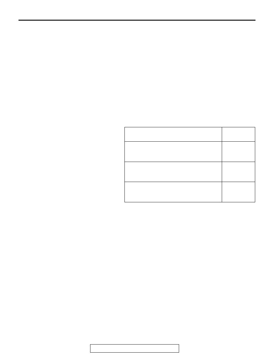
3. When the A/C is running after turning the A/C switch to ON, 

and the blower switch to the MH or HI position, check to be 
sure that the idle speed is at the standard value.

Standard value:

NOTE: It depends on the outside air temperature signal 
whether a low load, a middle load or a high load is applied to 
the air conditioning. The PCM receives the signal via the 
automatic compressor controller and determines whether 
the air conditioning is working under high, middle or low 
load.

VEHICLE CONDITION

IDLE-UP 
SPEED r/min

When the air conditioning is working under 
low load (Outside air temperature sensor: 
ON)

700 

± 50

When the air conditioning is working under 
middle load (Outside air temperature 
sensor: OFF)

800 

± 50

When the air conditioning is working under 
high load (Outside air temperature sensor: 
OFF)

1,000 

± 50

HEATER CONTROL ASSEMBLY, A/C SWITCH AND INSIDE/OUTSIDE CHANGEOVER SWITCH

TSB Revision

HEATER, AIR CONDITIONING AND VENTILATION

55A-120

HEATER CONTROL ASSEMBLY, A/C SWITCH AND 

INSIDE/OUTSIDE CHANGEOVER SWITCH

REMOVAL AND INSTALLATION

M1552012400047

INSTALLATION SERVICE POINTS

.

>>A<< AIR OUTLET CHANGEOVER DAMPER LEVER 
CABLE INSTALLATION
1. Set the air outlet changeover control knob on the heater 

control assembly to the defroster position.

2. Set the air outlet changeover damper lever of the 

heater/cooler unit to the defroster position as shown in the 
illustration, and then connect the cable to the link pin.

3. Push the outer cable in the direction of the arrow so that 

there is no looseness, and then secure it with the clip.

4. After installation, ensure that each damper operates 

smoothly by operating the heater control assembly knob.

.

>>B<< AIR MIX DAMPER LEVER CABLE INSTALLATION
1. Set the temperature control knob on the heater control 

assembly to the maximum hot position.

Pre-removal and Post-installation Operation
• Front Driver's Side Under Cover Removal and Installation (Refer to GROUP 52A, Instrument Pane

P.52A-3

.)

• Floor Console Removal and Installation (Refer to GROUP 52A, Floor Console 

P.52A-7

.)

• Foot Duct C and Foot Duct D Removal and Installation (Refer to 

P.55A-149

.)

AC000934 AB

1

2

3

4

REMOVAL STEPS

1.

CENTER PANEL (REFER TO 
GROUP 52A, INSTRUMENT 
PANEL 

P.52A-3

.)

>>B<<

2.

AIR MIX DAMPER LEVER CABLE

>>A<<

3.

AIR OUTLET CHANGEOVER 
DAMPER LEVER CABLE

4.

HEATER CONTROL ASSEMBLY

REMOVAL STEPS (Continued)

AC000932 AB

DEFROSTER POSITION

FACE POSITION

HEATER CONTROL ASSEMBLY, A/C SWITCH AND INSIDE/OUTSIDE CHANGEOVER SWITCH

TSB Revision

HEATER, AIR CONDITIONING AND VENTILATION

55A-121

2. Set the air mix damper lever of the heater/cooler unit to the 

maximum hot position as shown in the illustration, and then 
connect the cable to the lever pin.

3. Push the outer cable in the direction of the arrow so that 

there is no looseness, and then secure it with the clip.

INSPECTION

M1552012500055

DEFROSTER SWITCH CONTINUITY CHECK

Follow the table below to check the defroster switch for continu-
ity.

AC000933 AC

MAXIMUM HOT POSITION

MAXIMUM COOL 
POSITION

AIR OUTLET 
CHANGEOVER CONTROL 
KNOB POSITION

TESTER 
CONNECTION 

SPECIFIED 
CONDITION

At the "DEFROSTER" or 
"DEFROSTER/FOOT" 
position

− 3

Less than 2 
ohms

At the other positions

− 3

Less than 2 
ohms

AC001398

HEATER
CONTROL
ASSEMBLY

AB

HEATER CONTROL ASSEMBLY, A/C SWITCH AND INSIDE/OUTSIDE CHANGEOVER SWITCH

TSB Revision

HEATER, AIR CONDITIONING AND VENTILATION

55A-122

BLOWER SWITCH ASSEMBLY CONTINUITY 
CHECK

.

BLOWER SWITCH
Follow the table below to check the blower switch for continuity.

.

A/C SWITCH
Follow the table below to check the A/C switch for continuity.

.

INSIDE/OUTSIDE AIR CHANGEOVER SWITCH
Follow the table below to check the inside/outside air 
changeover switch for continuity.

SWITCH 
POSITION

TESTER 
CONNECTION 

SPECIFIED 
CONDITION

0 (OFF)

− 3, 3 − 4, 3 − 5, 3 − 6 Open circuit

1 (LO)

− 5

Less than 2 ohms

2 (ML)

− 1

Less than 2 ohms

3 (MH)

− 6

Less than 2 ohms

4 (HI)

− 4

Less than 2 ohms

SWITCH 
POSITION

TESTER 
CONNECTION 

SPECIFIED 
CONDITION

OFF

− 6

Open circuit

ON

− 6

Less than 2 ohms

SWITCH 
POSITION

TESTER 
CONNECTION 

SPECIFIED 
CONDITION

Inside air

− 5

Open circuit

Outside air

− 5

Less than 2 ohms

AC001399

CONNECTOR A

CONECTOR B

OFF

ON

OFF

ON

A/C SWITCH

AB


Content   ..  617  618  619  620   ..