Mitsubishi Montero (2004+). Manual - part 594
MANUAL A/C DIAGNOSIS
TSB Revision
HEATER, AIR CONDITIONING AND VENTILATION
55A-19
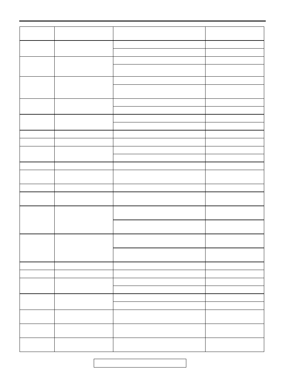
3
air thermo sensor power
supply
Ignition switch and A/C switch: OFF
0 V
Ignition switch and A/C switch: ON
5 V
4
Request signal for
tuning the A/C
compressor
Dual pressure switch: ON
0 V
Dual pressure switch: OFF
Battery positive voltage
5
PSM communication
line
When the A/C is OFF
0 V
When the A/C (compressor) is
operating
Battery positive voltage
6
Defogger relay
Defogger switch: ON
0 V
Defogger switch: OFF
Battery positive voltage
7
A/C switch
(inside/outside)
Inside: ON
Battery positive voltage
Outside: ON
0 V
8
Defroster switch (FOOT) Defroster switch FOOT position
10 V
9
Defroster switch (DEF)
Defroster switch DEF position
10 V
10
A/C switch (A/C switch) A/C switch: ON
0 V
A/C switch: OFF
10 V
11
Ground
At all times
0 V
13
Indicator (inside/outside
switch)
When inside /outside switch is ON
0 V
14
Indicator (A/C switch)
When A/C switch is ON
0 V
15
Indicator (defogger
switch)
When defogger switch is ON
0 V
16
Inside/outside air
changeover damper
motor (inside)
When the damper flap is moving to the
inside air recirculation position
0.5 V
When the damper flap is moving to the
outside air recirculation position
10 V (when the motor is
stopped)
17
Inside/outside air
changeover damper
motor (outside)
When the damper flap is moving to the
outside air recirculation position
0.5 V
When the damper flap is moving to the
inside air recirculation position
10 V (when the motor is
stopped)
18
Backup power supply
At all times
Battery positive voltage
19
Blower switch (LO)
Blower switch LO position
Battery positive voltage
20
Defogger switch
Defogger switch: ON
0 V
Defogger switch: OFF
10 V
21
A/C compressor clutch
relay
A/C compressor clutch relay: ON
Battery positive voltage
A/C compressor clutch relay: OFF
0 V
22
A/C compressor lock
signal (ignition signal)
Engine speed: 3,000 r/min
0.3
− 3.0 V
23
Lock sensor power
supply
Ignition switch ON
5 V
24
Ground to the lock
sensor
At all times
0 V
TERMINAL
NO.
INSPECTION ITEM
INSPECTION REQUIREMENT
NORMAL CONDITION