Mitsubishi Montero (2004+). Manual - part 550


  Index      Mitsubishi     Mitsubishi Montero - service repair manual 2004 year


Search            


Content   ..  548  549  550  551   ..


Mitsubishi Montero (2004+). Manual - part 550


RADIO WITH TAPE PLAYER AND CD PLAYER

TSB Revision

CHASSIS ELECTRICAL

54A-169

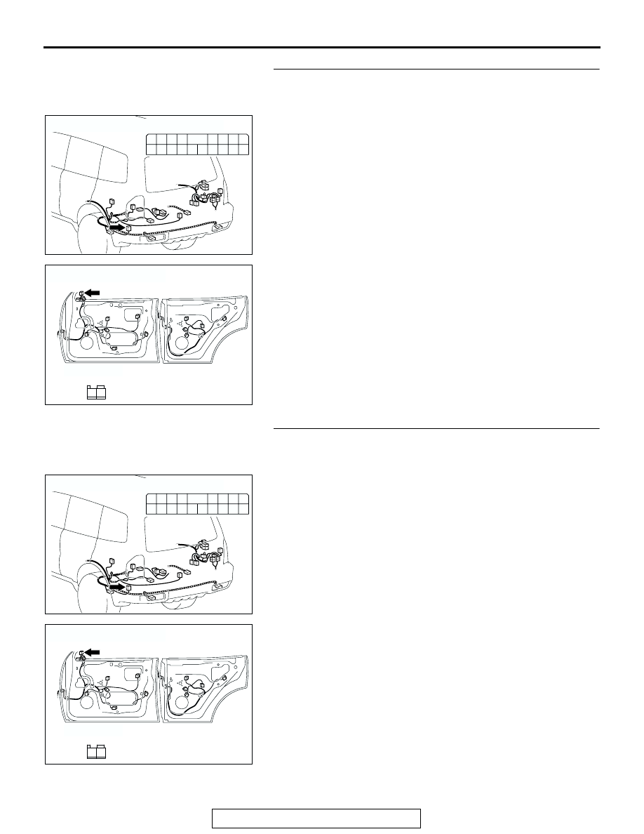
STEP 23. Check tweeter (RH) connector H-15 and amplifier 
connector G-19 for loose, corroded or damaged terminals, 
or terminals pushed back in the connector.
Q:  Are tweeter (RH) connector H-15 and amplifier 

connector G-19 in good condition?
YES : 
Go to Step 24.
NO :  Repair or replace the damaged component(s). Refer 

to GROUP 00E, Harness Connector Inspection 

P.00E-2

. The tweeter (RH) should sound.

STEP 24. Check the wiring harness between tweeter (RH) 
connector H-15 (terminals 1 and 2) and amplifier connector 
G-19 (terminals 12 and 4).

AC204179

CONNECTOR : G-19

AV

HARNESS SIDE

3 2

1110

4

1312

1
9

5

6

1615

7

8

1817

14

AC204181

CONNECTOR :  H-15

AI

HARNESS SIDE

1

2

AC204179

CONNECTOR : G-19

AV

HARNESS SIDE

3 2

1110

4

1312

1
9

5

6

1615

7

8

1817

14

AC204181

CONNECTOR :  H-15

AI

HARNESS SIDE

1

2

RADIO WITH TAPE PLAYER AND CD PLAYER

TSB Revision

CHASSIS ELECTRICAL

54A-170

NOTE: Also check intermediate connectors D-15 and D-124. If 
intermediate connector D-15 or D-124 are damaged, repair or 
replace the connector as described in GROUP 00E, Harness 
Connector Inspection 

P.00E-2

.

Q: Is the wiring harness between tweeter (RH) connector 

H-15 (terminals 1 and 2) and amplifier connector G-19 
(terminals 12 and 4) in good condition?
YES : 
Go to Step 25.
NO :  Repair the wiring harness. The tweeter (RH) should 

sound.

STEP 25. Replace the radio and CD player.
Q:  Do the speakers sound?

YES : There is no action to be taken.
NO :  Repair or replace the amplifier. The tweeter (RH) 

should sound.

STEP 26. Check the woofer.

(1) Remove the woofer. Refer to 

P.54A-190

.

(2) Check that the woofer generates noise when a five-volt 

voltage is applied on the woofer terminal.

Q: Is the woofer generating noise?

YES : Go to Step 27.
NO :  Replace the woofer. The woofer should sound.

AC204171

CONNECTOR : D-15

AB

10

9

31

30

20 21

7

6

28

17 18

8

19

29

4

3

25 26

14 15

1

23

12

2

13

24

5

16

27

11

22

32

AC204170

CONNECTOR : D-124

CW

3

9

2

8

6

5

7

4

1

ACX01868AB

5V

RADIO WITH TAPE PLAYER AND CD PLAYER

TSB Revision

CHASSIS ELECTRICAL

54A-171

STEP 27. Check woofer connector G-01 and amplifier 
connector G-19 for loose, corroded or damaged terminals, 
or terminals pushed back in the connector.
Q:  Are woofer connector G-01 and amplifier connector 

G-19 in good condition?
YES : 
Go to Step 28.
NO :  Repair or replace the damaged component(s). Refer 

to GROUP 00E, Harness Connector Inspection 

P.00E-2

The woofer should sound.

STEP 28. Check the wiring harness between woofer 
connector G-01 (terminals 1 and 2) and amplifier connector 
G-19 (terminals 8 and 18).

Q: Is the wiring harness between woofer connector G-01 

(terminal 1 and 2) and amplifier connector G-19 
(terminal 4 and 13) in good condition?
YES : 
Go to Step 29.
NO :  Repair the wiring harness. The woofer should sound.

AC204197

CONNECTORS : G-01, G-19

AE

G-19

HARNESS SIDE

G-19

HARNESS SIDE

G-01(B)

2

1

G-01(B)

3 2

1110

4

1312

1
9

5

6

1615

7

8

1817

14

AC204197

CONNECTORS : G-01, G-19

AE

G-19

HARNESS SIDE

G-19

HARNESS SIDE

G-01(B)

2

1

G-01(B)

3 2

1110

4

1312

1
9

5

6

1615

7

8

1817

14

RADIO WITH TAPE PLAYER AND CD PLAYER

TSB Revision

CHASSIS ELECTRICAL

54A-172

STEP 29. Replace the radio and CD player.
Q:  Do the speakers sound?

YES : There is no action to be taken.
NO :  Repair or replace the amplifier. The woofer should 

sound.

INSPECTION PROCEDURE 5: Noise is Present while Moving (AM).

STEP 1. Ask the driver about the noise.
(1) Find out the following information from the owner.
(2) Place where the noise occurs.
(3) Locality conditions (valley, mountain, etc.)
(4) Name and frequency of stations affected by noise

Q: What type of noise is detected, vehicle noise or 

external noise?

Vehicle noise : 

It may not be possible to prevent 

noise if the signal is weak. Go to step 2.

External noise : 

In almost all cases, prevention on 

the receiver side is next to impossible when 
the signal is weak. Go to Step 4.

STEP 2. Ask the driver about the location where 
the noise occurs

Q: Does the noise occur when entering or near a 

particular structure (building, tunnel, mountain, 
etc.)?

YES : 

Go to Step 3.

NO : 

Go to Step 4.

STEP 3. Check if the noise can be eliminated by 
adjusting the radio.
(1) Adjust the radio as follows.
(2) Change to a different station with a stronger 

signal. This will boost the systems resistance to 
outside interference.

(3) Suppress high tones to reduce noise.

Q: Has the noise been eliminated?

YES : 

The noise has now been eliminated. Inform 

the customer that it is normal to hear noise 
while receiving a weak station.

NO : 

Go to Step 4.

STEP 4. Check for the noise.

Q: Does noise still exist? 

YES : 

If there is still more noise than on other 

similar radio’s find out the type of noise. Ask 
the owner for the name and frequency of the 
affected stations, and consult with the radio 
manufacturer service center.

NO : 

System is operating normally.

INSPECTION PROCEDURE 6: Noise is Present while Moving (FM).

.

DIAGNOSIS
NOTE: FM waves have the same properties as light, 
and can be deflected and blocked. FM signal recep-
tion is severely degraded in the shadow of obstruc-
tions such as buildings or mountains. An FM receiver 
will then only receive a reflected signal.

ACX01869

10kW
OUTPUT FM
BROAD CAST

FOR STEREO:
20 - 25 km
(12 - 16 miles)

FOR  MONAURAL:
30 - 40 km (19 - 25 miles)

FOR  HOME STEREO:
80 - 90 km (50 - 56 miles)

MALTIPATH INTERFERENCE

FIRST FADING
INTERFERENCE

AC


Content   ..  548  549  550  551   ..