Mitsubishi Montero (2004+). Manual - part 541


  Index      Mitsubishi     Mitsubishi Montero - service repair manual 2004 year


Search            


Content   ..  539  540  541  542   ..


Mitsubishi Montero (2004+). Manual - part 541


RADIO WITH TAPE PLAYER AND CD PLAYER

TSB Revision

CHASSIS ELECTRICAL

54A-133

.

CIRCUIT OPERATION
Power is supplied from the battery directly to the 
amplifier.

.

TECHNICAL DESCRIPTION (COMMENT)
The cause is probably a faulty amplifier power supply 
circuit system.

.

TROUBLESHOOTING HINTS

• Damaged wiring harness or connector.

• Damaged DIN cable.

• Malfunction of the amplifier.

• Malfunction of the radio and tape player.

DIAGNOSIS

Required Special Tool:

• MB991223: Harness set

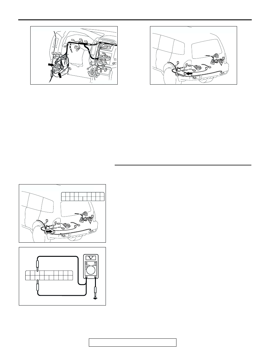
STEP 1. Measure at amplifier connector G-19 in order to 
check the battery circuit of power supply system to the 
amplifier.

(1) Disconnect amplifier connector G-19, and measure at the 

wiring harness side.

(2) Measure the voltage between terminal 6 and ground.

• The voltage should equal approximately 12 volts (bat-

tery positive voltage).

(3) Measure the voltage between terminal 16 and ground.

• The voltage should equal approximately 12 volts (bat-

tery positive voltage).

Q: Is the measured voltage approximately 12 volts (battery 

positive voltage)?
YES : 
Go to Step 4.
NO :  Go to Step 2.

AC204170EN

CONNECTOR: D-27, D-125

D-125

D-27

AC204179

CONNECTOR : G-19

AM

AC204179

CONNECTOR : G-19

AV

HARNESS SIDE

3 2

1110

4

1312

1
9

5

6

1615

7

8

1817

14

AC204738 EQ

HARNESS SIDE: G-19

3 2

11 10

4

13 12

1
9

5

6

16 15

7

8

18 17

14

RADIO WITH TAPE PLAYER AND CD PLAYER

TSB Revision

CHASSIS ELECTRICAL

54A-134

STEP 2. Check amplifier connector G-19 for loose, 
corroded or damaged terminals, or terminals pushed back 
in the connector.
Q: Is amplifier connector G-19 in good condition?

YES : Go to Step 3.
NO :  Repair or replace the damaged component(s). Refer 

to GROUP 00E, Harness Connector Inspection 

P.00E-2

. The speakers should sound.

STEP 3. Check the wiring harness between amplifier 
connector G-19 (terminal 6 and 16) and the battery.

NOTE: Also check intermediate connector D-27 and D-125. If 
intermediate connectors D-27 or D-125 are damaged, repair or 
replace the connector as described in GROUP 00E, Harness 
Connector Inspection 

P.00E-2

.

Q: Is the wiring harness between amplifier connector G-19 

(terminal 6 and 16) and the battery in good condition?
YES : 
There is no action to be taken.
NO :  Repair the wiring harness. The speakers should 

sound.

AC204179

CONNECTOR : G-19

AV

HARNESS SIDE

3 2

1110

4

1312

1
9

5

6

1615

7

8

1817

14

AC204179

CONNECTOR : G-19

AV

HARNESS SIDE

3 2

1110

4

1312

1
9

5

6

1615

7

8

1817

14

AC204188CR

CONNECTORS: D-27, D-125

D-125

D-27

D-27

D-125

9

8

6 7

5

3 4

20

32

21

33

43

17 18

30

41

16

29

28

39 40

13

25

12

24

35 36

14

26

37

15

27

38

19

31

42

1

10

22

2

11

23

34

RADIO WITH TAPE PLAYER AND CD PLAYER

TSB Revision

CHASSIS ELECTRICAL

54A-135

STEP 4. Measure at amplifier connector G-19 in order to 
check the ground circuit to the amplifier.
(1) Disconnect amplifier connector G-19, and measure at the 

wiring harness side.

(2) Measure the resistance between terminal 7 and ground.

• The resistance should equal 2 ohms or less.

(3) Measure the resistance between terminal 17 and ground.

• The resistance should equal 2 ohms or less.

Q: Is the measured resistance 2 ohms or less?

YES : Go to Step 7.
NO :  Go to Step 5.

STEP 5. Check amplifier connector G-19 for loose, 
corroded or damaged terminals, or terminals pushed back 
in the connector.

Q: Is amplifier connector G-19 in good condition?

YES : Go to Step 6.
NO :  Repair or replace the damaged component(s). Refer 

to GROUP 00E, Harness Connector Inspection 

P.00E-2

. The speakers should sound.

STEP 6. Check the wiring harness between amplifier 
connector G-19 (terminal 7 and 17) and ground.

Q: Is the wiring harness between amplifier connector G-19 

(terminal 7 and 17) and ground in good condition?
YES : 
There is no action to be taken.
NO :  Repair the wiring harness. The speakers should 

sound.

AC204179

CONNECTOR : G-19

AV

HARNESS SIDE

3 2

1110

4

1312

1
9

5

6

1615

7

8

1817

14

AC204738 EJ

HARNESS SIDE: G-19

3 2

11 10

4

13 12

1
9

5

6

16 15

7

8

18 17

14

AC204179

CONNECTOR : G-19

AV

HARNESS SIDE

3 2

1110

4

1312

1
9

5

6

1615

7

8

1817

14

AC204179

CONNECTOR : G-19

AV

HARNESS SIDE

3 2

1110

4

1312

1
9

5

6

1615

7

8

1817

14

RADIO WITH TAPE PLAYER AND CD PLAYER

TSB Revision

CHASSIS ELECTRICAL

54A-136

STEP 7. Check the DIN cable between amplifier and radio 
and CD player.
Q: Is the DIN cable in good condition?

YES : Go to Step 8.
NO :  Repair or replace the DIN cable. The speakers should 

sound.

STEP 8. Replace the radio and CD player.
Q:  Do the speakers sound normally?

YES : There is no action to be taken.
NO :  Repair or replace the amplifier. The speakers should 

sound.


Content   ..  539  540  541  542   ..