Mitsubishi Montero (2004+). Manual - part 527


  Index      Mitsubishi     Mitsubishi Montero - service repair manual 2004 year


Search            


Content   ..  525  526  527  528   ..


Mitsubishi Montero (2004+). Manual - part 527


COMBINATION METER ASSEMBLY AND VEHICLE SPEED SENSOR

TSB Revision

CHASSIS ELECTRICAL

54A-77

INSPECTION

M1543019501783

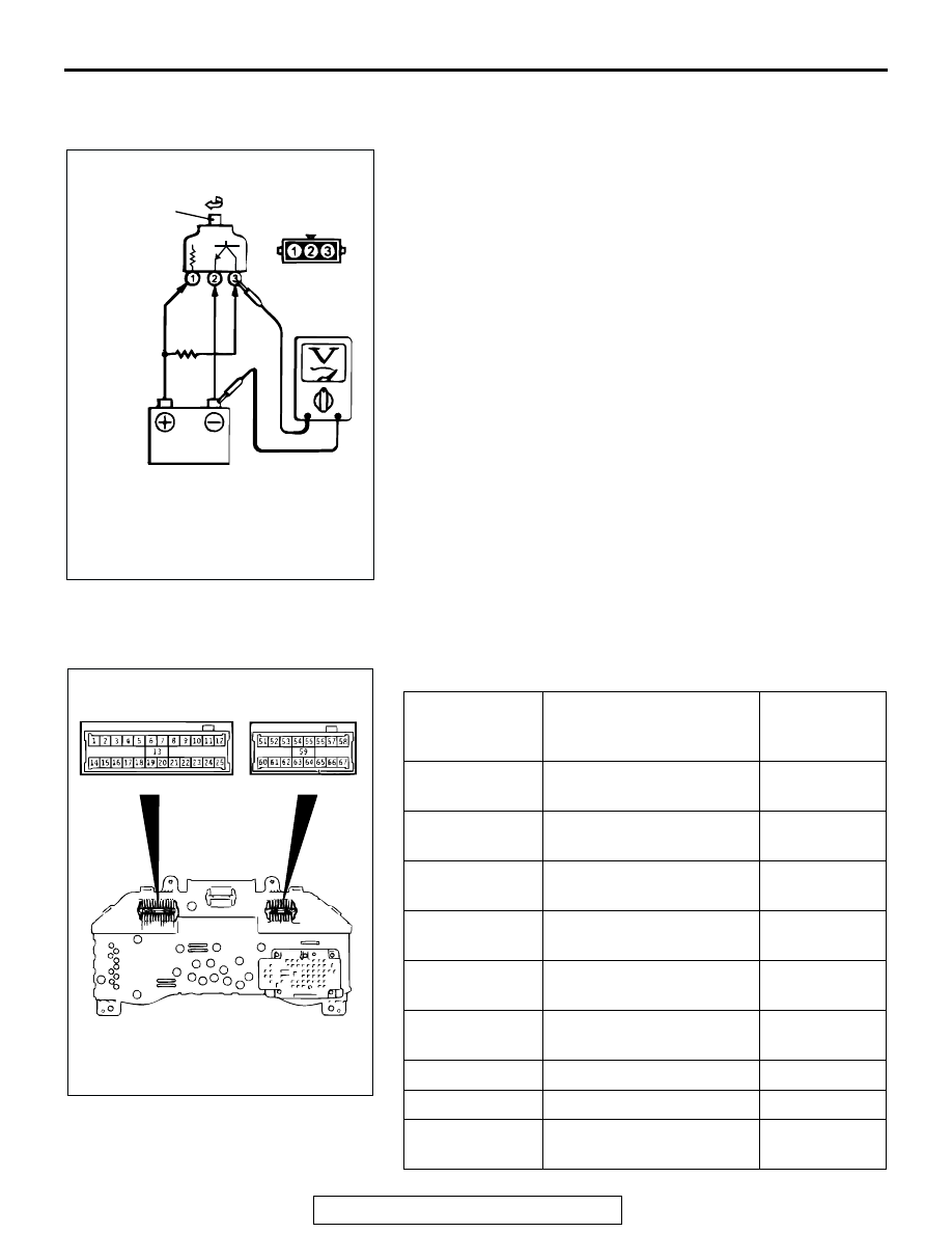
VEHICLES SPEED SENSOR CHECK

1. Remove the vehicle speed sensor and connect a 3 

− 10 kilo 

ohms resistor as shown in the illustration.

2. Turn the shaft of the vehicle speed sensor and check that 

there is voltage between terminals 2 and 3. (1 turn = 4 
pulses)

3. If within the standard value, the vehicle speed sensor is OK.

If not within the standard value, replace the vehicle speed 
sensor.

COMBINATION METER INTERNAL RESISTANCE 
CHECK

Measure the resistance between terminals using an ohmmeter.

AC102349AB

TURN

SHAFT

RESISTOR
3 - 10

TERMINAL NO. 
TO MEASURE 
RESISTANCE

TERMINAL NAME

STANDARD 
VALUE

25 

− 67

Battery power supply and 
ground

1 M

Ω or more

11 

− 67

Battery power supply and 
ground

1 M

Ω or more

25 

− 62

IG power supply and 
ground

1 M

Ω or more

11 

− 62

IG power supply and 
ground

1 M

Ω or more

63 

− 67

 Battery power supply and 
fuel gauge 

1 M

Ω or more 

62 

− 63

IG power supply and fuel 
gauge 

1 M

Ω or more 

25 

− 63

Fuel gauge and ground 

180 

11 

− 63

Fuel gauge and ground 

180 

64 

− 67

Battery power supply and 
water temperature gauge 

1 M

Ω or more 

ACX00783

D-03

D-05

AB

COMBINATION METER ASSEMBLY AND VEHICLE SPEED SENSOR

TSB Revision

CHASSIS ELECTRICAL

54A-78

 DISASSEMBLY AND ASSEMBLY

M1543003100158

62 

− 64

IG power supply and water 
temperature gauge 

1 M

Ω or more 

25 

− 64

Water temperature gauge 
and ground 

210 

11 

− 64

Water temperature gauge 
and ground 

210 

TERMINAL NO. 
TO MEASURE 
RESISTANCE

TERMINAL NAME

STANDARD 
VALUE

ACX00784AC

1

3

6

10

11

12

13

14

4

5

15

8

7

9

2

DISASSEMBLY STEPS

1. GLASS
2. WINDOW PLATE 
3. SPEEDOMETER 
4. TACHOMETER 
5. FUEL GAUGE, WATER 

TEMPERATURE GAUGE 
ASSEMBLY 

6. TRIP METER KNOB 
7. INDICATOR PLATE 

8. INDICATOR PRISM 
9. INDICATOR LENS 
10. INSTRUMENT PANEL PRINTED 

CIRCUIT BOARD 

11. COMBINATION METER CASE 
12. INDICATOR CASE 
13. COMBINATION PLATE "A" 
14. COMBINATION PLATE "B" 
15. COMBINATION PLATE "C" 

DISASSEMBLY STEPS (Continued)

HEADLIGHT, FRONT SIDE MARKER LIGHT AND POSITION LIGHT ASSEMBLY

TSB Revision

CHASSIS ELECTRICAL

54A-79

HEADLIGHT, FRONT SIDE MARKER LIGHT AND 

POSITION LIGHT ASSEMBLY

HEADLIGHT DIAGNOSIS

M1542010500241

The headlights are controlled by the Simplified Wir-
ing System (SWS). For troubleshooting, refer to 
GROUP 54B, SWS Diagnosis 

− Symptom Chart 

P.54B-22

.

ON-VEHICLE SERVICE

HEADLIGHT AIMING

M1542000900390

PRE-AIMING INSTRUCTIONS

1. Inspect for badly rusted or faulty headlight assemblies.
2. These conditions must be corrected before a satisfactory 

adjustment can be made.

3. Inspect tire inflation, and adjust if necessary.
4. If the fuel tank is not full, place a weight in luggage room of 

vehicle to simulate weight of a full tank [3 kg (6.5 pounds) 
per gallon.]

5. There should be no other load in the vehicle other than 

driver or substituted weight of approximately 70 kg (150 
pounds) placed in driver's position.

6. Thoroughly clean headlight lenses.
7. Place the vehicle on a level floor, perpendicular to a flat 

screen 7.62 m (25.0 feet) away from the bulb center-marks 
on the headlight lens.

8. Rock vehicle sideways to allow vehicle to assume its normal 

position.

9. Bounce the front suspension through three (3) oscillations 

by applying the body weight to hood or bumper.

10.Set the distance between the screen and the bulb center 

marks of the headlight as shown in the illustration.

ACX01793 AB

CENTER MARK

HEADLIGHT, FRONT SIDE MARKER LIGHT AND POSITION LIGHT ASSEMBLY

TSB Revision

CHASSIS ELECTRICAL

54A-80

11.Four lines of adhesive tape (or equivalent markings) are 

required on screen or wall:

(1) Position a vertical tape or mark so that it is aligned with 

the vehicle center line.

(2) Measure the distance from the center-marks on the 

headlight lens to the floor. Transfer the measurement to 
the screen. Horizontal tape or mark on the screen is for 
reference of vertical adjustment.

(3) Measure the distance from the center line of the vehicle 

to the center of each headlight. Transfer the 
measurement to the screen. Vertical tape or mark on the 
screen with reference to the center line of each headlight 
bulb.

HEADLIGHT ADJUSTMENT

1. The low beam headlight will project on the screen upper 

edge of the beam (cut-off).

2. Turn the adjusting screws to achieve the specified low-beam 

cut-off location on the aiming screen.

Standard value:
(Vertical direction) 53 mm (2.1 inches) (0.4

°) below hor-

izontal (H) 
Limit:
(Vertical direction) Standard value 

± 50 mm (± 2.0 

inches) (

± 0.38°)

3. When adjusting headlight, disconnect the other headlight 

harness.

CAUTION

Do not cover a headlight for more than three minutes to 
prevent the plastic headlight lens deformation.
4. There is no horizontal aim adjustment. Horizontal aim is 

preset and does not require adjustment. High-beam pattern 
should be correct when the low-beams are adjusted 
properly.

LUMINOUS INTENSITY MEASUREMENT

M1542001000118

1. Set the headlights to high-beam
2. Using a photometer, and following its manufacturer's 

instruction manual, measure the headlight center intensity 
and check to be sure that the limit value is satisfied.

Limit: 40,000 cd or more {When a screen is set 18.3m 
(60 feet) ahead of the vehicle}

AC005167

(1)

(2)

(3)

HEADLIGHT CENTER

VEHICLE CENTER  
LINE

SCREEN

(3)

7.62m (25.0 ft)

AB

AC101777

VERTICAL ADJUSTING

AB

ACX01800

DISTANCE OF
VERTICAL 
DIRECTION

HEADLIGHT
CENTER

HIGH INTENSITY

ZONE

15

(H)

(V)

AB


Content   ..  525  526  527  528   ..