Mitsubishi Montero (2004+). Manual - part 495
TIRE PRESSURE MONITORING SYSTEM (TPMS) DIAGNOSIS
TSB Revision
WHEEL AND TIRE
31-51
STEP 2. After the tire inflation pressure is adjusted and the
TPMS transmitter sends inflation pressure information on
it, check the TPMS warning light.
(1) Wait until the tires cool down, and adjust all the tire inflation
pressures (including spare tire) to the value specified on the
tire pressure label.
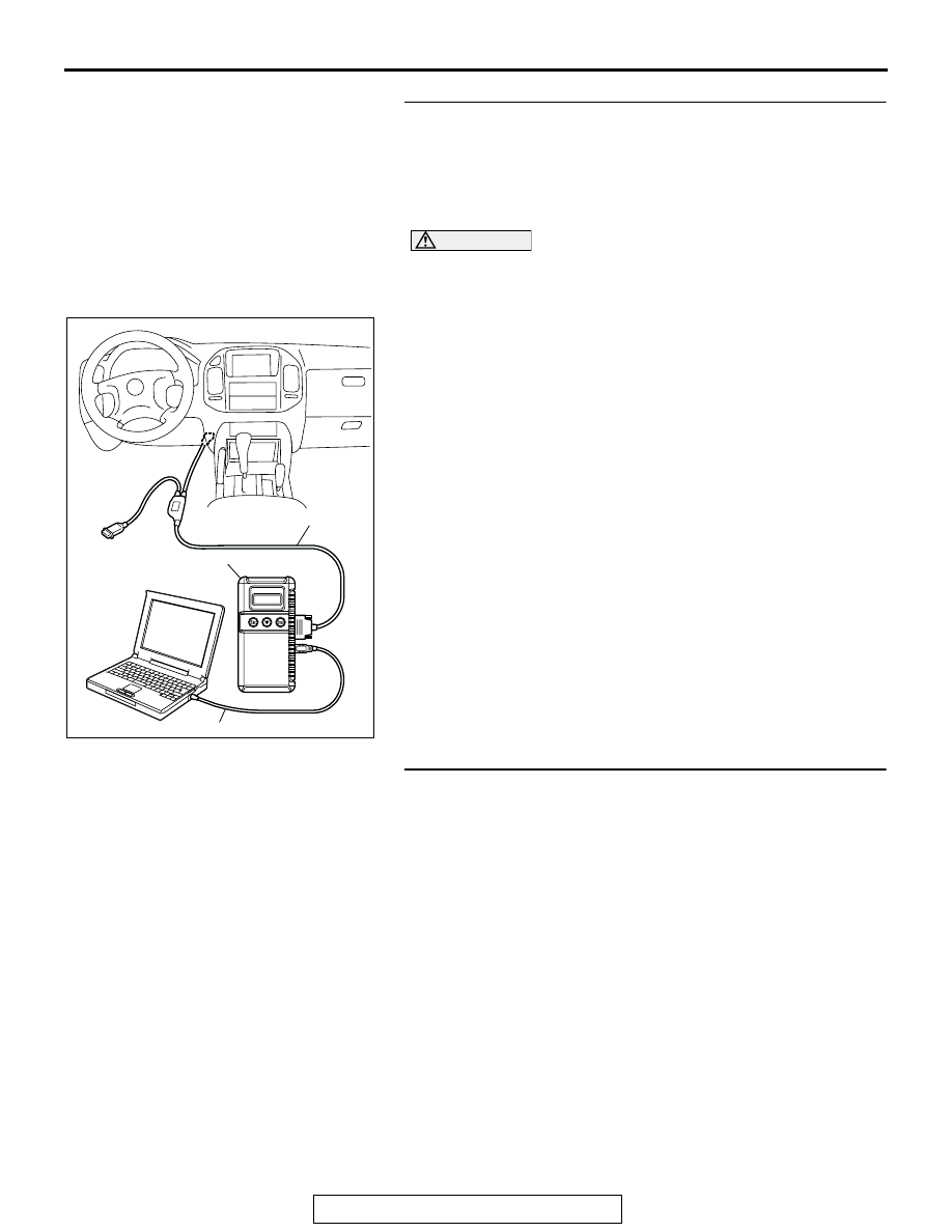
CAUTION
To prevent damage to scan tool MB991958, always turn the
ignition switch to the "LOCK" (OFF) position before con-
necting or disconnecting scan tool MB991958.
(2) Connect scan tool MB991958 to the data link connector.
(3) Turn the ignition switch to the "ON" position.
(4) Execute "Tire Pressure Sensor Check" on scan tool
MB991958 "Special Function" (Refer to
(5) Check the TPMS warning light.
Q: Is the TPMS warning light turned off?
YES : The procedure is complete.
NO : Go to Step 3.
STEP 3. Check the tire inflation pressure again.
Use a tire pressure gauge to check that all the tire inflation
pressures (including spare tire) meet the value specified on the
tire pressure label.
Q: Are all the tires (including spare tire) in good condition?
YES : Go to Step 4.
NO : Replace the valve grommet or valve core, or repair
the damaged tire. Replace the tire if necessary. And
then return to Step 2.
AC306409AF
MB991911
MB991824
MB991827