Mitsubishi Montero (2004+). Manual - part 438


  Index      Mitsubishi     Mitsubishi Montero - service repair manual 2004 year


Search            


Content   ..  436  437  438  439   ..


Mitsubishi Montero (2004+). Manual - part 438


TRANSFER

TSB Revision

AUTOMATIC TRANSMISSION OVERHAUL

23B-79

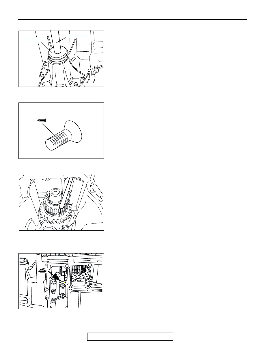
>>B<< OIL SEAL INSTALLATION
1. Use special tools MB990929 and MB990938 to install the oil 

seal.

2. Apply MITSUBISHI genuine grease Part number 0101011 or 

equivalent to the lip of the oil seal.

.

>>C<< REAR BEARING RETAINER INSTALLATION
Apply MITSUBISHI genuine sealant part number MD997740 or 
equivalent to the threads.
NOTE: The new bolt is precoated with sealant, so sealant does 
not need to be applied.

.

>>D<< SNAP RING INSTALLATION
Select and install the snap ring which adjusts the H-L clutch 
hub end play to the standard value.

Standard value: 0 

 0.08 mm (0  0.003 inch)

.

>>E<< H-L SHIFT FORK/H-L CLUTCH SLEEVE 
INSTALLATION
Apply MITSUBISHI genuine grease Part number 0101011 or 
equivalent to the high-low shift fork lift inserting part at indicated 
in drawing. Install the high-low shift fork and the high low clutch 
sleeve in the combined state onto the transfer case.

.

AKX00211

MB990938

MB990932

AB

AKX00212

AKX00213

AKX00214

TRANSFER

TSB Revision

AUTOMATIC TRANSMISSION OVERHAUL

23B-80

>>F<< SPACER INSTALLATION
1. Place pieces of solder [approximately 10 mm (0.4 inch) in 

length and 1.6 mm (0.06 inch) in diameter] in the transfer 
case housing as shown.

2. Install the countershaft gear into the transfer case.
3. Install the transfer case plate and tighten the bolts.

4. Using a micrometer, measure the thickness of the crushed 

solder. Based on the result, select a spacer which adjusts 
the end play to the standard value shown below.

Standard value: 0 

 0.15 mm (0  0.006 inch)

NOTE:  If the solder is not crushed, repeat steps 1 and 2 
using thicker solder.

.

>>G<< TRANSFER CASE PLATE INSTALLATION
1. Apply MITSUBISHI genuine grease Part number 0101011 or 

equivalent to the high-low shift rail inserting part indicated in 
the drawing.

2. Face the notched section of the input gears in the direction 

shown in the illustration.

AKX00215

SOLDER

AB

AKX00165

AKX00217

AKX00218

TRANSFER

TSB Revision

AUTOMATIC TRANSMISSION OVERHAUL

23B-81

CAUTION

Squeeze the sealant out evenly to apply it in an unbroken, 
non-excessive quantity.
3. Apply MITSUBISHI genuine sealant Part number 

MD997740 or equivalent to the transfer case.

CAUTION

In case the sub-gear is difficult to engage the counter shaft 
gear, install securely by rotating the transfer drive shaft 
and such.
4. Install the transfer case plate together with the input gear. 

Slide the input gear tooth aligned in Step 2 along the tooth 
space of the countershaft gear.

.

>>H<< SNAP RING INSTALLATION
Select and install the snap ring which adjusts the differential 
lock hub end play to the standard value.

Standard value: 0 

 0.08 mm (0  0.003 inch)

.

>>I<< STEEL BALL/SPACER INSTALLATION
Install the steel ball at the indicated location on the transfer 
drive shaft, and then install so that the oil groove of spacer is 
the chain cover side.

.

>>J<< 2-4WD SHIFT FORK/2-4WD CLUTCH SLEEVE 
INSTALLATION
Apply MITSUBISHI genuine grease Part number 0101011 or 
equivalent to 2-4WD shift fork shaft inserting part indicated in 
drawing, and then install the 2-4WD shift fork and the 2-4WD 
clutch sleeve in combined state on the transfer case.

.

AKX00219

AKX00220

AKX00221

STEEL BALL

AB

AKX00222

TRANSFER

TSB Revision

AUTOMATIC TRANSMISSION OVERHAUL

23B-82

>>K<< SNAP RING INSTALLATION
Select and install the snap ring which adjusts the 2-4WD clutch 
hub end play to the standard value.

Standard value: 0 

 0.08 mm (0  0.003 inch)

.

>>L<< SYNCHRONIZER OUTER RING/SYNCHRONIZER 
CONE/SYNCHRONIZER INNER RING INSTALLATION
1. Push the synchronizer outer ring, synchronizer corn and the 

synchronizer inner ring into the drive sprocket in combined 
state, and then measure the indicated dimension of the drive 
sprocket and synchronizer outer ring.

LIMIT: 0.3 mm (0.012 inch)

2. In case that the value is out of limit, exchange as the 

synchronizer ring set.

3. Combine the synchronizer outer ring, the synchronizer cone 

and the synchronizer inner ring, and install them by mating 
the notch of 2-4WD clutch hub and protrusion of the 
synchronizer outer ring.

.

>>M<< DRIVE SPROCKET/FRONT OUTPUT SHAFT/CHAIN 
INSTALLATION
1. Engage the chain to the drive sprocket and the sprocket of 

front output shaft.

AKX00223

AKX00224

AKX00225


Content   ..  436  437  438  439   ..