Mitsubishi Montero (2004+). Manual - part 389
CHARGING SYSTEM
TSB Revision
ENGINE ELECTRICAL
16-11
12.Increase the engine speed to 2,500 r/min.
13.Read the value displayed on the voltmeter when
the current output by the generator becomes 10 A
or less.
14.If the voltage reading is within the value in the
voltage regulation table, then the voltage regulator
is operating normally.
If the voltage is outside the standard value, there
is a malfunction of the voltage regulator or the
generator (Refer to the following table).
15.After the test, lower the engine speed to the idle
speed.
16.Turn the ignition switch to the "LOCK" (OFF)
position.
17.Disconnect the negative battery cable.
18.Disconnect the ammeter, voltmeter and engine
tachometer.
19.Connect the generator output wire to the
generator "B" terminal.
20.Connect the negative battery cable.
VOLTAGE REGULATION TABLE
WAVE PATTERN CHECK USING AN
OSCILLOSCOPE
M1161001200180
.
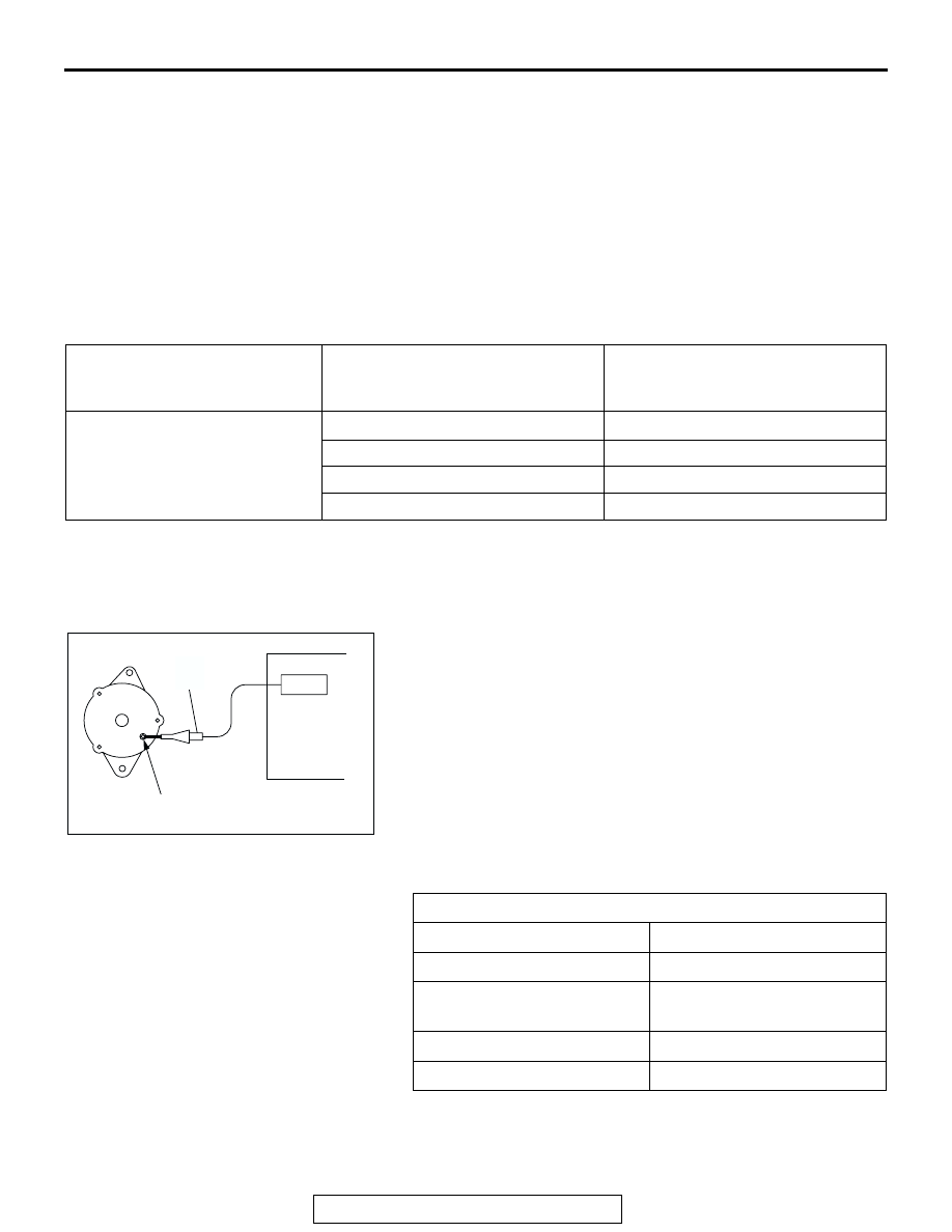
MEASUREMENT METHOD
Connect the oscilloscope special patterns pick-up to the gener-
ator "B" terminal.
.
STANDARD WAVEFORM
INSPECTION TERMINAL
VOLTAGE REGULATOR
AMBIENT TEMPERATURE [
°C
(
°F)]
STANDARD VALUE (V)
Terminal "S"
−20 (−4)
14.2
− 15.4
20 (68)
13.9
− 14.9
60 (140)
13.4
− 14.5
80 (176)
13.1
− 14.5
AKX00188
GENERATOR
OSCILLOSCOPE
"B" TERMINAL
PROBE
AB
Observation Conditions
FUNCTION
SPECIAL PATTERNS
Pattern height
Variable
Variable knob
Adjust while viewing the wave
pattern
Pattern selector
Raster
Engine revolutions
Curb idle speed