Mitsubishi Montero (2004+). Manual - part 386
SPECIFICATIONS
TSB Revision
INTAKE AND EXHAUST
15-15
SPECIFICATIONS
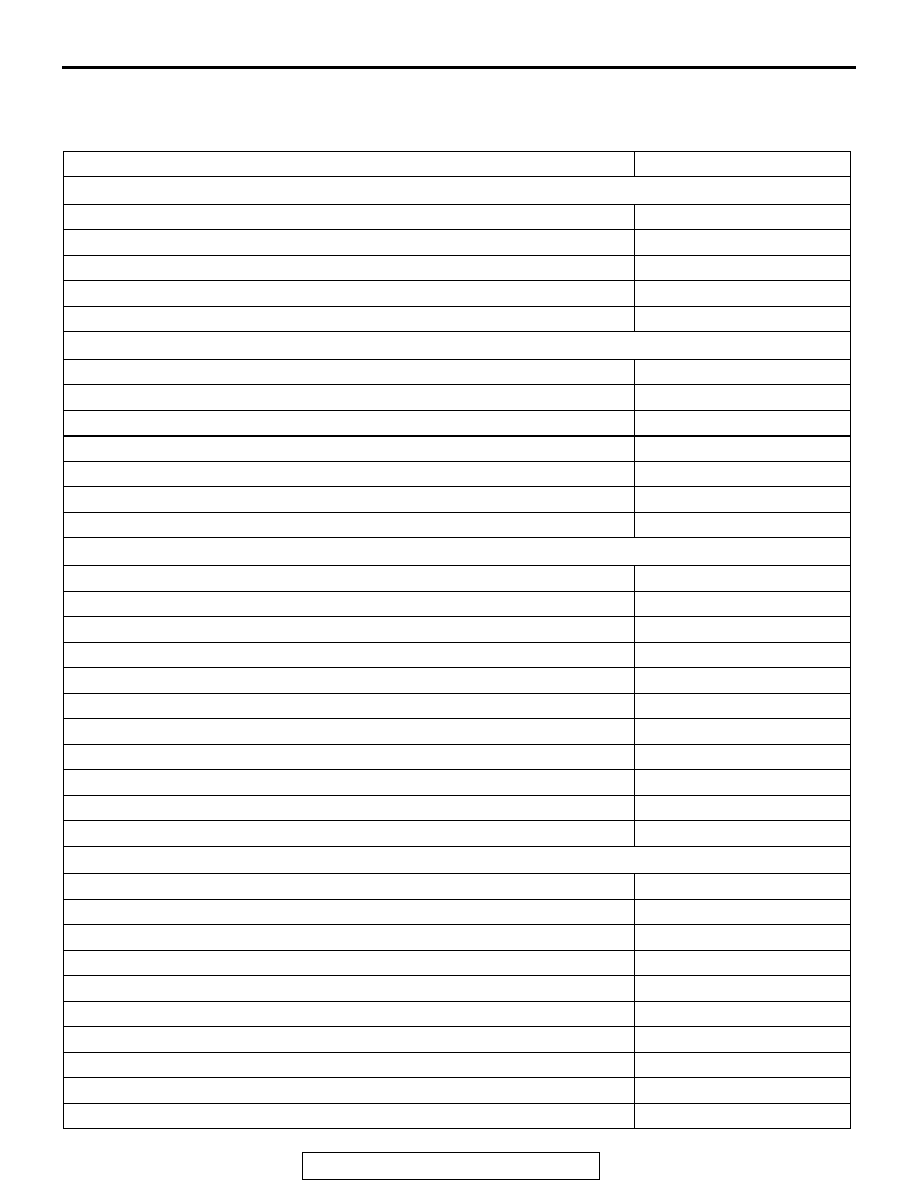
FASTENER TIGHTENING SPECIFICATIONS
M1151006800391
ITEM
SPECIFICATION
Air cleaner
Air cleaner bolt
9.0
± 1.0 N⋅m (80 ± 9 in-lb)
Air cleaner bracket bolt
9.0
± 1.0 N⋅m (80 ± 9 in-lb)
Air duct bolt
5.0
± 1.0 N⋅m (44 ± 9 in-lb)
Volume airflow sensor nut
9.0
± 1.0 N⋅m (80 ± 9 in-lb)
Air intake hose clamp bolt
3.9
± 1.0 N⋅m (35 ± 8 in-lb)
Exhaust manifold
EGR pipe bolt
18
± 2 N⋅m (13 ± 2 ft-lb)
EGR pipe flare nut
59
± 10 N⋅m (44 ± 7 ft-lb)
Engine oil dipstick guide bolt
14
± 1 N⋅m (120 ± 13 in-lb)
Exhaust manifold nut
44
± 5 N⋅m (33 ± 3 ft-lb)
Heat protector bolt
14
± 1 N⋅m (120 ± 13 in-lb)
Transmission fluid dipstick guide to engine hanger bolt
24
± 4 N⋅m (18 ± 3 ft-lb)
Transmission fluid dipstick guide to transmission bolt
44
± 8 N⋅m (33 ± 5 ft-lb)
Exhaust pipe and main muffler
Bracket bolt
49
± 10 N⋅m (37 ± 7 ft-lb)
Warm-up three-way catalytic converter bolt
49
± 4 N⋅m (37 ± 3 ft-lb)
Warm-up three-way catalytic converter nut
49
± 10 N⋅m (37 ± 7 ft-lb)
Front exhaust pipe bolt
25
± 4 N⋅m (18 ± 3 ft-lb)
Front exhaust pipe nut
49
± 10 N⋅m (37 ± 7 ft-lb)
Ground cable bolt
9.0
± 2.0 N⋅m (79 ± 18 in-lb)
Hanger bolt
13
± 2 N⋅m (111 ± 22 in-lb)
Hanger bracket bolt
13
± 2 N⋅m (111 ± 22 in-lb)
Heated oxygen sensor
44
± 5 N⋅m (33 ± 3 ft-lb)
Main muffler bolt
49
± 10 N⋅m (37 ± 7 ft-lb)
Main muffler nut
49
± 10 N⋅m (37 ± 7 ft-lb)
Intake manifold
Control wiring harness clamp bolt
11
± 1 N⋅m (98 ± 8 in-lb)
EGR pipe flare nut
59
± 10 N⋅m (44 ± 7 ft-lb)
EGR pipe bolt
18
± 2 N⋅m (13 ± 2 ft-lb)
EGR valve bolt
24
± 3 N⋅m (18 ± 2 ft-lb)
Evaporative emission purge solenoid valve bolt
9.0
± 1.0 N⋅m (80 ± 9 in-lb)
Fuel high-pressure hose bolt
5.0
± 1.0 N⋅m (44 ± 9 in-lb)
Fuel pipe bolt
9.0
± 1.0 N⋅m (80 ± 9 in-lb)
Fuel pressure regulator bolt
9.0
± 2.0 N⋅m (80 ± 17 in-lb)
Fuel rail bolt
12
± 1 N⋅m (102 ± 13 in-lb)
Intake manifold tuning valve bolt and nut
9.0
± 1.0 N⋅m (80 ± 9 in-lb)