Mitsubishi Montero (2004+). Manual - part 354


  Index      Mitsubishi     Mitsubishi Montero - service repair manual 2004 year


Search            


Content   ..  352  353  354  355   ..


Mitsubishi Montero (2004+). Manual - part 354


MULTIPORT FUEL INJECTION (MFI) DIAGNOSIS

TSB Revision

MULTIPORT FUEL INJECTION (MFI)

13A-903

STEP 2. Check the evaporative emission ventilation 
solenoid.
Refer to GROUP 17, Emission Control System 

− Evaporative 

Emission Ventilation Solenoid Check 

P.17-68

.

Q: Is the evaporative emission ventilation solenoid 

normal?
YES : 
Check the following items, and repair or replace the 

defective items.
a.Check for leaks from the vapor line or 

evaporative emission canister.

b.Check for leaks from the fuel tank.

Then confirm that the malfunction symptom is 

eliminated.

NO :  Repair or replace it. Then confirm that the malfunction 

symptom is eliminated.

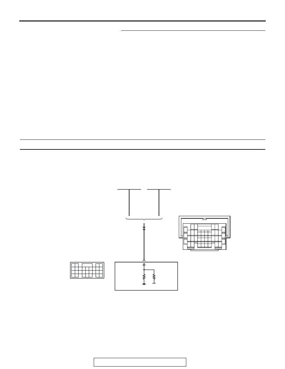
INSPECTION PROCEDURE 26: Incorrect Idle Speed When the A/C is Operating (A/C Switch 2 Signal)

GREEN

AK201155

YELL

OW

-

RED

GREEN

6

AUTOMATIC
COMPRESSOR
CONTROLLER

POWERTRAIN
CONTROL
MODULE (PCM)

AUTOMATIC
A/C SYSTEM

MANUAL
A/C SYSTEM

78

A/C-ECU

9

6

10

17

18

29

2

3 4

7 8

19 20

30 31

12

11

24

33 34 35

21

32

27

26

36 37

28

38

25

13

15

14

16

23

22

1

5

E-111

A/C Switch 2 Signal

61
656667686970 717273
74757677787980 8182
8384

858687

8889

62

6364

D-134

(MU803804)

MULTIPORT FUEL INJECTION (MFI) DIAGNOSIS

TSB Revision

MULTIPORT FUEL INJECTION (MFI)

13A-904

.

CIRCUIT OPERATION

• The PCM increases the engine idle speed by 

driving the Throttle actuator control motor when 
the automatic compressor-ECU sends a "A/C on" 
signal to the module.

• The automatic compressor-ECU detects how the 

air conditioning is applying load to the engine, 
and converts the information to a voltage signal 
(High voltage = low load, Low voltage = high 
load). This voltage signal is called "A/C switch 2 

signal". The PCM receives this A/C switch 2 sig-
nal from the automatic compressor-ECU through 
terminal No. 78, and determines the idle-up 
speed according to the high or low air condition-
ing load.

.

TROUBLESHOOTING HINTS (The most likely 
causes for this code to be set are: ) 

• Malfunction of the A/C control system.

• Open or shorted circuit, or improper connector 

contact.

• PCM failed. 

DIAGNOSIS

STEP 1. Check harness connector D-134 at PCM for 
damage.
Q: Is the harness connector in good condition?

YES :  Go to Step 2.
NO :  Repair or replace it. Refer to GROUP 00E, Harness 

Connector Inspection 

P.00E-2

. Then confirm that the 

malfunction symptom is eliminated.

AK201038

CONNECTOR: D-134

AD

PCM

D-134(GR)

AK201060

E-111

AB

CONNECTOR: E-111

AK201166

61

62

63

64

65

66

67

68

69

70

71

76

77

78

79

85

86

87

80

72

73

74

75

81

82

83

84

88

89

CONNECTOR: D-134

AB

PCM

D-134(GR)

HARNESS CONNECTOR: 
COMPONENT SIDE

MULTIPORT FUEL INJECTION (MFI) DIAGNOSIS

TSB Revision

MULTIPORT FUEL INJECTION (MFI)

13A-905

STEP 2. Measure the output voltage at PCM harness side 
connector D-134.
(1) Disconnect the connector D-134 and measure at the 

harness side.

(2) Start the engine and run at idle.
(3) Turn the A/C switch "ON".

(4) Measure the voltage between terminal No. 78 and ground.

• If atmospheric air temperature is 15°C (59°F) or less, 

the voltage should be 1 volt or less.

• If atmospheric air temperature is 18°C (65.4°F) or more, 

the voltage should be battery positive voltage.

(5) Turn the A/C switch "OFF".
(6) Turn the ignition switch to the "LOCK" (OFF) position.
Q: Is the voltage normal?

YES :  Replace the PCM. Then confirm that the malfunction 

symptom is eliminated.

NO :  Refer to GROUP 55, Introduction To Heater, Air 

Conditioning And Ventilation Diagnosis 

P.55A-5

.

AK201166

61

62

63

64

65

66

67

68

69

70

71

76

77

78

79

85

86

87

80

72

73

74

75

81

82

83

84

88

89

CONNECTOR: D-134

AB

PCM

D-134(GR)

HARNESS CONNECTOR: 
COMPONENT SIDE

AK201458

61

62

63

64

65

66

67

68

69

70

71

76

77

78

79

85

86

87

80

72

73

74

75

81

82

83

84

88

89

D-134 HARNESS 
CONNECTOR: 
COMPONENT SIDE

AK201458AB

61

62

63

64

65

66

67

68

69

70

71

76

77

78

79

85

86

87

80

72

73

74

75

81

82

83

84

88

89

MULTIPORT FUEL INJECTION (MFI) DIAGNOSIS

TSB Revision

MULTIPORT FUEL INJECTION (MFI)

13A-906

INSPECTION PROCEDURE 27: A/C condenser fan is inoperative

.

CIRCUIT OPERATION

• The battery positive voltage is applied on the 

PCM (terminal No. 17) from the condensor fan 
control relay.

• When the PCM switches on its power transistor, 

the condensor fan control relay coil is energized, 
causing current to flow in the circuit.

.

TROUBLESHOOTING HINTS (The most likely 
causes for this code to be set are: ) 

• Malfunction of the condensor fan control relay.

• Malfunction of the condenser fan motor.

• Improper connector contact, open or 

short-circuited harness wire.

• PCM failed. 

AK201156

LIGHT GREEN-

RED

LIGHT GREEN-

RED

17

3 4

8

6

5

11

10

12

9

7

1 2

A-03

(MU802611)

11

POWERTRAIN
CONTROL
MODULE (PCM)

CONDENSER FAN
RELAY

A/C Condenser Fan Circuit

1

2

3

5

6 7 8 9

4

20

21 22

232425

2627

10111213

14 15

16 1718

19

D-132

(MU803802)

AK201038

CONNECTOR: D-132

AB

PCM

D-132(GR)

AK201046

A-03(B)

AB

CONNECTOR: A-03


Content   ..  352  353  354  355   ..