Mitsubishi Montero (2004+). Manual - part 326


  Index      Mitsubishi     Mitsubishi Montero - service repair manual 2004 year


Search            


Content   ..  324  325  326  327   ..


Mitsubishi Montero (2004+). Manual - part 326


MULTIPORT FUEL INJECTION (MFI) DIAGNOSIS

TSB Revision

MULTIPORT FUEL INJECTION (MFI)

13A-791

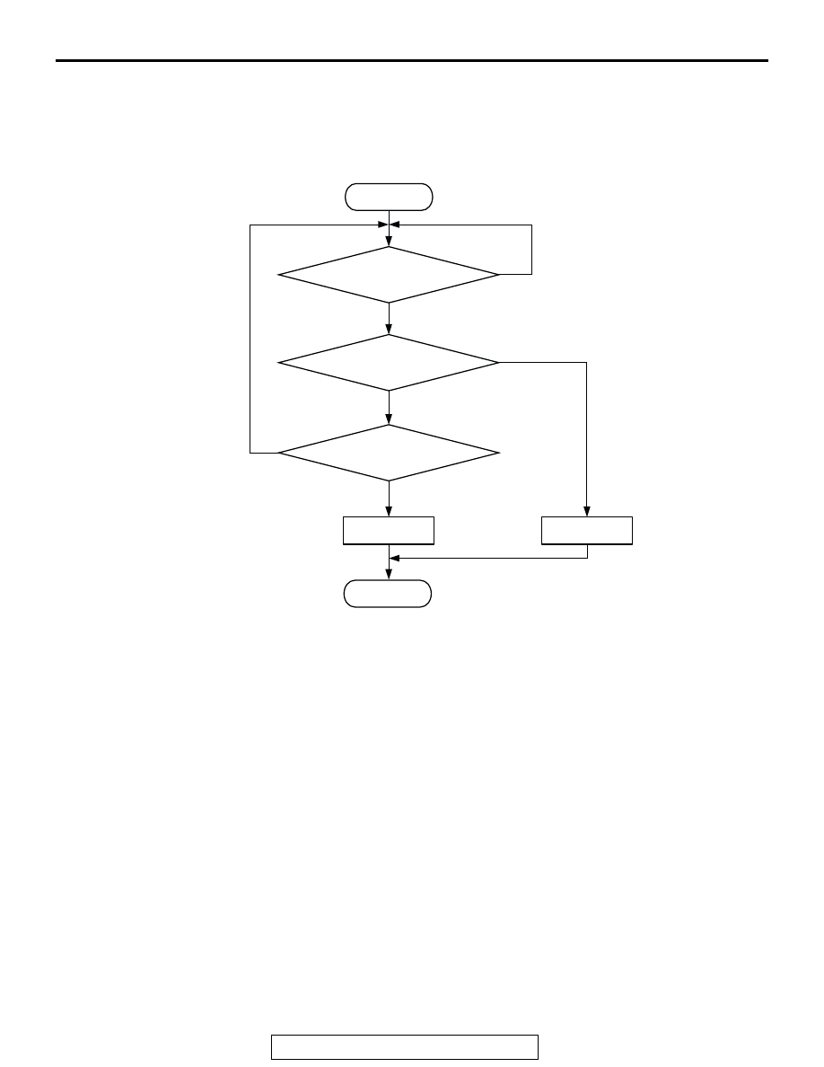
DTC SET CONDITIONS <Range/Performance problem 

 relation between main and sub>

Logic Flow Chart

.

Check Condition

• Ignition switch "ON" position.

• Accelerator pedal position sensor (main) output 

voltage is between 0.2 and 4.5 volts.

• Accelerator pedal position sensor (sub) output 

voltage is between 0.2 and 4.5 volts.

• Change of accelerator pedal position sensor 

(sub) output voltage per 25 miliseconds is lower 
than 0.06 volt.

Judgement Criteria

• Voltage obtained with the formula given below is 

1.0 volt or higher for 0.2 second: [accelerator 
pedal position sensor (main) output voltage 

− 

accelerator pedal position sensor (sub) output 
voltage +0.3 volt].

.

OBD-II DRIVE CYCLE PATTERN
None.

.

TROUBLESHOOTING HINTS (The most likely 
causes for this code to be set are:)

• APS failed.

• Harness damage, or connector damage in APS 

circuit.

• PCM failed.

DIAGNOSIS

Required Special Tools:

• MB991958: Scan Tool (MUT-III Sub Assembly)

START

END

NO

NO

YES

YES

YES

NO

MALFUNCTION

GOOD

CONTINUOUS

FAILURE FOR 0.2secs

MONITORING

CONDITIONS

AK302967

APS (MAIN) -

{APS (SUB) +0.3V}

> =1.0V

MULTIPORT FUEL INJECTION (MFI) DIAGNOSIS

TSB Revision

MULTIPORT FUEL INJECTION (MFI)

13A-792

• MB991824: V.C.I.

• MB991827: USB Cable

• MB991911: Main Harness B

STEP 1. Check connector D-138 at accelerator pedal 
position sensor for damage.
Q: Is the connector in good condition?

YES : Go to Step 2.
NO :  Repair or replace it. Refer to GROUP 00E, Harness 

Connector Inspection 

P.00E-2

. Then go to Step 17.

STEP 2. Check the accelerator pedal position sensor.
(1) Disconnect the accelerator pedal position sensor connector 

D-138.

(2) Measure resistance between terminal No.1 and No. 2 and 

between terminal No. 7 and No. 8.

Standard value: 3.5 

 6.5 k

(3) Measure resistance between terminal No. 2 and No. 3 and 

between terminal No. 6 and No. 8.

(4) Move the accelerator pedal from the idle position to the 

full-open position.

• Resistance value changes in accordance with the accel-

erator pedal depression smoothly.

Q: Is the resistance normal?

YES : Go to Step 3.
NO :  Replace the accelerator pedal position sensor. Then 

go to Step 17.

AK200945

3

4

5

1

2

8

6

7

AB

CONNECTOR: D-138

HARNESS 
CONNECTOR: 
COMPONENT SIDE

D-138(GR)

AK200945

3

4

5

1

2

8

6

7

AB

CONNECTOR: D-138

HARNESS 
CONNECTOR: 
COMPONENT SIDE

D-138(GR)

6 7 8

1 2 3 4 5

AK201450

ACCELERATOR PEDAL
POSITION SENSOR
SIDE CONNECTOR

AB

6 7 8

1 2 3 4 5

AK201451

ACCELERATOR PEDAL
POSITION SENSOR
SIDE CONNECTOR

AB

MULTIPORT FUEL INJECTION (MFI) DIAGNOSIS

TSB Revision

MULTIPORT FUEL INJECTION (MFI)

13A-793

STEP 3. Check the continuity at accelerator pedal position 
sensor harness side connector D-138.
(1) Disconnect the connector D-138 and measure at the 

harness side.

(2) Measure the continuity between terminal No. 1 and ground.

• Should be less than 2 ohms.

Q: Does continuity exist?

YES : Go to Step 7.
NO :  Go to Step 4.

STEP 4. Check connector D-135 at PCM for damage.
Q: Is the connector in good condition?

YES : Go to Step 5.
NO :  Repair or replace it. Refer to GROUP 00E, Harness 

Connector Inspection 

P.00E-2

. Then go to Step 17.

AK200945

3

4

5

1

2

8

6

7

AB

CONNECTOR: D-138

HARNESS 
CONNECTOR: 
COMPONENT SIDE

D-138(GR)

3

4

5

1

2

8

6

7

AK201452

D-138 HARNESS 
CONNECTOR: 
COMPONENT SIDE

AB

AK200947

91

92

93

94

95

96

97

98

99

100

101

102

103

104

105

106

107

108

109

110

111

112

113

114

115

116

117

118

119

120

CONNECTOR: D-135

HARNESS CONNECTOR: 
COMPONENT SIDE

AB

PCM

D-135(GR)

MULTIPORT FUEL INJECTION (MFI) DIAGNOSIS

TSB Revision

MULTIPORT FUEL INJECTION (MFI)

13A-794

STEP 5. Check for harness damage between accelerator 
pedal position sensor connector D-138 (terminal No. 1) and 
PCM connector D-135 (terminal No. 91).
Q: Is the harness wire in good condition?

YES : Go to Step 6.
NO :  Repair it. Then go to Step 17.

STEP 6. Using scan tool MB991958, read the diagnostic 
trouble code (DTC).

CAUTION

To prevent damage to scan tool MB991958, always turn the 
ignition switch to the "LOCK"(OFF) position before con-
necting or disconnecting scan tool MB991958.
(1) Connect scan tool MB991958 to the data link connector.
(2) Turn the ignition switch to the "ON" position.
(3) After the DTC has been deleted, read the DTC again.
(4) Turn the ignition switch to the "LOCK"(OFF) position.
Q: Is DTC P2138 set?

YES : Replace the PCM. Then go to Step 17.
NO :  It can be assumed that this malfunction is intermittent. 

Refer to GROUP 00, How to Use 
Troubleshooting/Inspection Service Points 

P.00-6

.

AK200945

3

4

5

1

2

8

6

7

AB

CONNECTOR: D-138

HARNESS 
CONNECTOR: 
COMPONENT SIDE

D-138(GR)

AK200947

91

92

93

94

95

96

97

98

99

100

101

102

103

104

105

106

107

108

109

110

111

112

113

114

115

116

117

118

119

120

CONNECTOR: D-135

HARNESS CONNECTOR: 
COMPONENT SIDE

AB

PCM

D-135(GR)

AK302970

AB

MB991911

MB991824

MB991827


Content   ..  324  325  326  327   ..