Mitsubishi Montero (2004+). Manual - part 299


  Index      Mitsubishi     Mitsubishi Montero - service repair manual 2004 year


Search            


Content   ..  297  298  299  300   ..


Mitsubishi Montero (2004+). Manual - part 299


MULTIPORT FUEL INJECTION (MFI) DIAGNOSIS

TSB Revision

MULTIPORT FUEL INJECTION (MFI)

13A-683

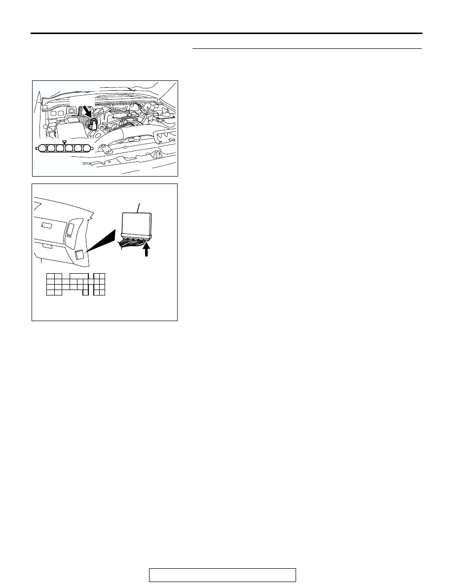
STEP 14. Check for harness damage between throttle 
actuator control motor connector B-05 (terminal No. 6) and 
PCM connector D-136 (terminal No. 133).
Q: Is the harness wire in good condition?

YES : Go to Step 15.
NO :  Repair it. Then go to Step 17.

AK201174

1

6 5 4 3 2

B-05(B)

CONNECTOR: B-05

HARNESS 
CONNECTOR: 
COMPONENT SIDE

AB

AK201170

121

122

123

124

125

126

127

128

129

130

131

132

133

134

135

136

137

138

139

140

141

142

143

144

145

146

CONNECTOR: D-136

PCM

D-136(GR)

HARNESS CONNECTOR: 
COMPONENT SIDE

AB

MULTIPORT FUEL INJECTION (MFI) DIAGNOSIS

TSB Revision

MULTIPORT FUEL INJECTION (MFI)

13A-684

STEP 15. Check for harness damage between throttle 
actuator control motor connector B-05 (terminal No. 5) and 
PCM connector D-136 (terminal No. 141).
Q: Is the harness wire in good condition?

YES : Go to Step 16.
NO :  Repair it. Then go to Step 17.

STEP 16. Using scan tool MB991958, read the diagnostic 
trouble code (DTC).

CAUTION

To prevent damage to scan tool MB991958, always turn the 
ignition switch to the "LOCK"(OFF) position before con-
necting or disconnecting scan tool MB991958.
(1) Connect scan tool MB991958 to the data link connector.
(2) Turn the ignition switch to the "ON" position.
(3) After the DTC has been deleted, read the DTC again.
(4) Turn the ignition switch to the "LOCK"(OFF) position.
Q: Is DTC P0638 set?

YES : Replace the PCM. Then go to Step 17.
NO :  It can be assumed that this malfunction is intermittent. 

Refer to GROUP 00, How to Use 
Troubleshooting/Inspection Service Points.

AK201174

1

6 5 4 3 2

B-05(B)

CONNECTOR: B-05

HARNESS 
CONNECTOR: 
COMPONENT SIDE

AB

AK201170

121

122

123

124

125

126

127

128

129

130

131

132

133

134

135

136

137

138

139

140

141

142

143

144

145

146

CONNECTOR: D-136

PCM

D-136(GR)

HARNESS CONNECTOR: 
COMPONENT SIDE

AB

AK302970

AB

MB991911

MB991824

MB991827

MULTIPORT FUEL INJECTION (MFI) DIAGNOSIS

TSB Revision

MULTIPORT FUEL INJECTION (MFI)

13A-685

STEP 17. Using scan tool MB991958, read the diagnostic 
trouble code (DTC).
(1) Connect scan tool MB991958 to the data link connector.
(2) Turn the ignition switch to the "ON" position.
(3) After the DTC has been deleted, read the DTC again.
(4) Turn the ignition switch to the "LOCK"(OFF) position.
Q:  Is DTC P0638 set?

YES : Retry the troubleshooting.
NO :  The inspection is complete.

DTC P0642: Throttle Position Sensor Power Supply

.

TECHNICAL DESCRIPTION

• PCM checks the TPS power voltage for abnormal 

conditions.

.

DESCRIPTIONS OF MONITOR METHODS
Throttle position sensor source voltage is smaller 

than the specified value.

.

MONITOR EXECUTION
Continuous

.

MONITOR EXECUTION CONDITIONS (Other 
monitor and Sensor)

Other Monitor (There is no temporary DTC stored 

in memory for the item monitored below)

• Not applicable

Sensor (The sensor below is determined to be 

normal)

• Not applicable

.

DTC SET CONDITIONS

Check Conditions

• Battery positive voltage is higher than 6.3 volts.

Judgement Criteria

• Throttle position sensor power voltage should be 

4.1 volts or less for 0.5 second.

.

OBD-II DRIVE CYCLE PATTERN
None.

.

TROUBLESHOOTING HINTS (The most likely 
causes for this code to be set are:)

• PCM failed.

DIAGNOSIS

Required Special Tools:

• MB991958: Scan Tool (MUT-III Sub Assembly)

• MB991824: V.C.I.

• MB991827: USB Cable

• MB991911: Main Harness B

AK302970

AB

MB991911

MB991824

MB991827

MULTIPORT FUEL INJECTION (MFI) DIAGNOSIS

TSB Revision

MULTIPORT FUEL INJECTION (MFI)

13A-686

STEP 1. Using scan tool MB991958, read the diagnostic 
trouble code (DTC).

CAUTION

To prevent damage to scan tool MB991958, always turn the 
ignition switch to the "LOCK"(OFF) position before con-
necting or disconnecting scan tool MB991958.
(1) Connect scan tool MB991958 to the data link connector.
(2) Turn the ignition switch to the "ON" position.
(3) After the DTC has been deleted, read the DTC again.
(4) Turn the ignition switch to the "LOCK"(OFF) position.
Q: Is DTC P0642 set?

YES : Replace the PCM.
NO :  It can be assumed that this malfunction is intermittent. 

Refer to GROUP 00, How to Use 
Troubleshooting/Inspection Service Points 

P.00-6

.

AK302970

AB

MB991911

MB991824

MB991827


Content   ..  297  298  299  300   ..