Mitsubishi Montero (2004+). Manual - part 296


  Index      Mitsubishi     Mitsubishi Montero - service repair manual 2004 year


Search            


Content   ..  294  295  296  297   ..


Mitsubishi Montero (2004+). Manual - part 296


MULTIPORT FUEL INJECTION (MFI) DIAGNOSIS

TSB Revision

MULTIPORT FUEL INJECTION (MFI)

13A-671

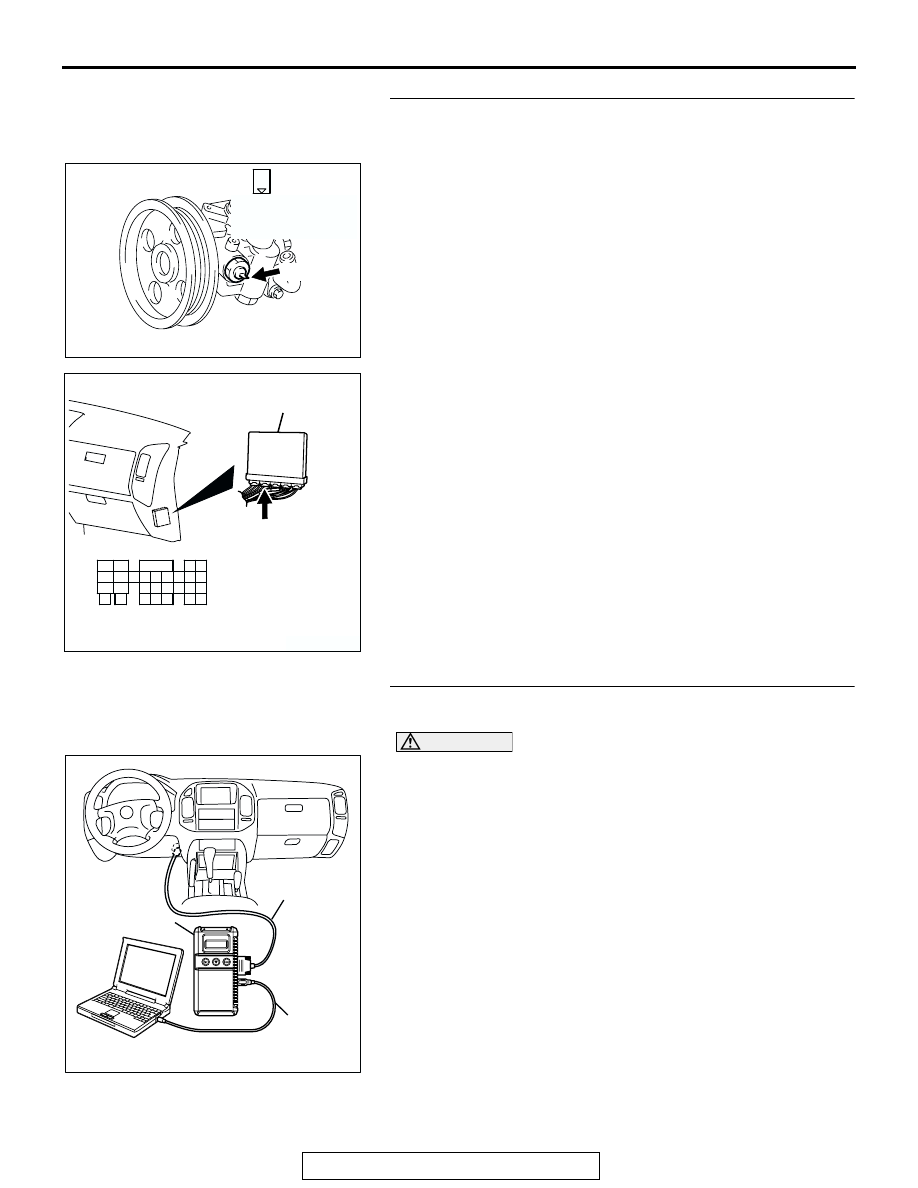
STEP 6. Check for harness damage between power 
steering pressure switch connector B-29 (terminal No. 1) 
and PCM connector D-133 (terminal No. 47).
Q: Is the harness wire in good condition?

YES : Replace the PCM. Then go to Step 7.
NO :  Repair it. Then go to Step 7.

STEP 7. Using scan tool MB991958, check data list item 27: 
Power Steering Pressure Switch.

CAUTION

To prevent damage to scan tool MB991958, always turn the 
ignition switch to the "LOCK" (OFF) position before con-
necting or disconnecting scan tool MB991958.
(1) Connect scan tool MB991958 to the data link connector.
(2) Start the engine and run at idle.
(3) Set scan tool MB991958 to the data reading mode for item 

27, Power Steering Pressure Switch.

• If the steering wheel is not turned while idling, "OFF" will 

be displayed.

• If the steering wheel is turned while idling, "ON" will be 

displayed.

(4) Turn the ignition switch to the "LOCK" (OFF) position.
Q: Is the switch operating properly?

YES : The procedure is complete.
NO :  Repeat the troubleshooting.

AK200973

1

AB

CONNECTOR: B-29

B-29(B)

HARNESS 
CONNECTOR: 
COMPONENT SIDE

AK200939

31

32

33

34

35

36

37

38

39

40

41

42

43

44

45

46

47

48

49

52

53

54

55

56

57

58

50

51

AB

CONNECTOR: D-133

HARNESS CONNECTOR: 
COMPONENT SIDE

PCM

D-133(GR)

AK302970

AB

MB991911

MB991824

MB991827

MULTIPORT FUEL INJECTION (MFI) DIAGNOSIS

TSB Revision

MULTIPORT FUEL INJECTION (MFI)

13A-672

DTC P0513: Immobilizer Malfunction

.

TECHNICAL DESCRIPTION

• PCM monitors the communication condition with 

the immobilizer-ECU and the message from the 
immobilizer-ECU, and when the abnormality is 
found, PCM makes the engine not to start.

.

DTC SET CONDITIONS

Check Conditions

• Ignition switch: ON

Judgment Criteria

• When the communication error between PCM 

and the immobilizer-ECU continues for 2 seconds 
or more.

.

TROUBLESHOOTING HINTS (The most likely 

causes for this code to be set are: )

• Malfunction of harness or connector.

• Malfunction of immobilizer-ECU.

• Malfunction of PCM.

DIAGNOSIS

Required Special Tools:

• MB991958: Scan Tool (MUT-III Sub Assembly)

• MB991824: V.C.I.

• MB991827: USB Cable

• MB991911: Main Harness B

STEP 1. Using scan tool MB991958, read the immobilizer 
diagnostic trouble code (DTC).

CAUTION

To prevent damage to scan tool MB991958, always turn the 
ignition switch to the "LOCK" (OFF) position before con-
necting or disconnecting scan tool MB991958.
(1) Connect scan tool MB991958 to the data link connector.
(2) Turn the ignition switch to the "ON" position.
(3) Read the immobilizer system-DTC.
(4) Turn the ignition switch to the "LOCK" (OFF) position.
Q: Is the immobilizer system 

 DTC is output?

YES : Refer to GROUP 54A, Ignition Switch and 

Immobilizer System 

− Diagnostic Trouble Code Chart 

P.54A-11

.

NO :  If DTC P0513 is output again after the MFI 

− DTC has 

been erased, replace the PCM. Then check that the 
DTC P0513 does not reset.

AK302970

AB

MB991911

MB991824

MB991827

MULTIPORT FUEL INJECTION (MFI) DIAGNOSIS

TSB Revision

MULTIPORT FUEL INJECTION (MFI)

13A-673

DTC P0606: Powertrain Control Module Main Processor Malfunction

.

TECHNICAL DESCRIPTION

• Throttle actuator control module processor 

checks the PCM for abnormal conditions.

.

DESCRIPTIONS OF MONITOR METHODS
No watch dog pulse is detected.

.

MONITOR EXECUTION
Continuous

.

MONITOR EXECUTION CONDITIONS (Other 
monitor and Sensor)

Other Monitor (There is no temporary DTC stored 

in memory for the item monitored below)

• Not applicable

Sensor (The sensor below is determined to be 

normal)

• Not applicable

.

DTC SET CONDITIONS

Check Conditions

• Ignition switch "ON" position.

Judgement Criteria

• No surveillance pulse signals should be input for 

0.5 second.

.

OBD-II DRIVE CYCLE PATTERN
None.

.

TROUBLESHOOTING HINTS (The most likely 
causes for this code to be set are:)

• PCM failed.

DIAGNOSIS

Required Special Tools:

• MB991958: Scan Tool (MUT-III Sub Assembly)

• MB991824: V.C.I.

• MB991827: USB Cable

• MB991911: Main Harness B

STEP 1. Using scan tool MB991958, read the diagnostic 
trouble code (DTC)

CAUTION

To prevent damage to scan tool MB991958, always turn the 
ignition switch to the "LOCK"(OFF) position before con-
necting or disconnecting scan tool MB991958.
(1) Connect scan tool MB991958 to the data link connector.
(2) Turn the ignition switch to the "ON" position.
(3) After the DTC has been deleted, read the DTC again.
(4) Turn the ignition switch to the "LOCK"(OFF) position.
Q: Is DTC P0606 set?

YES : Replace the PCM.
NO :  It can be assumed that this malfunction is intermittent. 

Refer to GROUP 00, How to Use 
Troubleshooting/Inspection Service Points 

P.00-6

.

AK302970

AB

MB991911

MB991824

MB991827

MULTIPORT FUEL INJECTION (MFI) DIAGNOSIS

TSB Revision

MULTIPORT FUEL INJECTION (MFI)

13A-674

DTC P0638: Throttle Actuator Control Motor Circuit Range/Performance Problem

.

Throttle Actuator Control Motor Circuit 
Range/Performance Problem Circuit

• Refer to, DTC P0657 − Throttle Actuator Control 

Motor Relay Circuit 

P.13A-687

.

• Refer to, DTC P2101 − Throttle Actuator Control 

Motor Magneto Malfunction 

P.13A-719

.

.

CIRCUIT OPERATION

• Refer to, DTC P0657 − Throttle Actuator Control 

Motor Relay Circuit 

P.13A-687

.

• Refer to, DTC P2101 − Throttle Actuator Control 

Motor Magneto Malfunction 

P.13A-719

.

.

TECHNICAL DESCRIPTION

• PCM checks the electronic controlled throttle sys-

tem for abnormal conditions.

.

DESCRIPTIONS OF MONITOR METHODS
Difference between throttle position sensor (main) 

output and target opening is greater than the 
specified value.

.

MONITOR EXECUTION
Continuous

.

MONITOR EXECUTION CONDITIONS (Other 
monitor and Sensor)

Other Monitor (There is no temporary DTC stored 

in memory for the item monitored below)

• Not applicable

Sensor (The sensor below is determined to be 

normal)

• Not applicable

.

DTC SET CONDITIONS

Check Conditions

• Battery positive voltage is higher than 8.3 volts.

• Throttle position sensor (main) output voltage is 

between 0.35 and 4.8 volts.

• Drop of throttle position sensor (main) output volt-

age per 100 milliseconds is more than 0.04 volt.

Judgement Criteria

• Throttle position sensor (main) output voltage has 

continued to be higher than the target throttle 
position sensor (main) voltage by 0.5 volt or more 
for 0.5 second.

Check Conditions

• Battery positive voltage is higher than 8.3 volts.

• Throttle position sensor (main) output voltage is 

between 0.35 and 4.8 volts.

Judgement Criteria

• Difference between throttle position sensor 

(main) output voltage and target throttle position 
sensor (main) voltage is 1 volt or higher for 4 sec-
onds.

.

OBD-II DRIVE CYCLE PATTERN
None.

.

TROUBLESHOOTING HINTS (The most likely 
causes for this code to be set are:)

• Throttle valve return spring failed.

• Throttle actuator control motor relay failed or mal-

adjusted.

• Open or shorted throttle actuator control motor 

relay circuit, harness damage, or connector dam-
age.

• Throttle valve operation failed.

• Throttle actuator control motor failed.

• Harness damage in throttle actuator control 

motor circuit, or connector damage.

• PCM failed.

DIAGNOSIS

Required Special Tools:

• MB991958: Scan Tool (MUT-III Sub Assembly)

• MB991824: V.C.I.

• MB991827: USB Cable

• MB991911: Main Harness B


Content   ..  294  295  296  297   ..