Mitsubishi Montero (2004+). Manual - part 268
MULTIPORT FUEL INJECTION (MFI) DIAGNOSIS
TSB Revision
MULTIPORT FUEL INJECTION (MFI)
13A-559
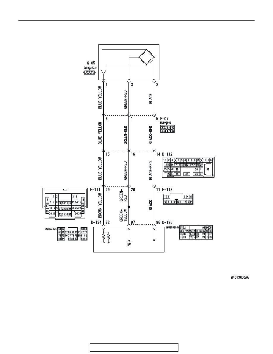
FUEL TANK
DIFFERENTIAL
PRESSURE
SENSOR
POWERTRAIN CONTROL
MODULE (PCM)
AC309251
Fuel Tank Differential Pressure Sensor Circuit
AB
FUEL TANK
DIFFERENTIAL
PRESSURE
SENSOR
POWERTRAIN CONTROL
MODULE (PCM)
AC309251