Mitsubishi Montero (2004+). Manual - part 243


  Index      Mitsubishi     Mitsubishi Montero - service repair manual 2004 year


Search            


Content   ..  241  242  243  244   ..


Mitsubishi Montero (2004+). Manual - part 243


MULTIPORT FUEL INJECTION (MFI) DIAGNOSIS

TSB Revision

MULTIPORT FUEL INJECTION (MFI)

13A-459

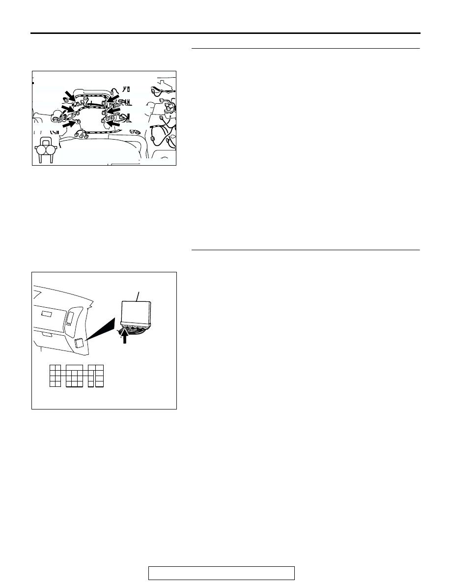
STEP 4. Check harness connector B-01, B-33, B-02, B-35, 
B-03, B-11 at injector for damage.

a. Check the harness connector B-01 at No. 1 cylinder injec-

tor.

b. Check the harness connector B-33 at No. 2 cylinder injec-

tor.

c. Check the harn.ess connector B-02 at No. 3 cylinder injec-

tor.

d. Check the harness connector B-35 at No. 4 cylinder injec-

tor.

e. Check the harness connector B-03 at No. 5 cylinder injec-

tor.

f. Check the harness connector B-11 at No. 6 cylinder 

injector.

Q: Is the harness connector in good condition?

YES : Go to Step 5.
NO :  Repair or replace the injector. Refer to GROUP 00E, 

Harness Connector Inspection 

P.00E-2

. Then go to 

Step 9.

STEP 5. Check harness connector D-132 at PCM for 
damage.
Q: Is the harness connector in good condition?

YES : Go to Step 6.
NO :  Repair or replace it. Refer to GROUP 00E, Harness 

Connector Inspection 

P.00E-2

. Then go to Step 9.

AK200960

1

2

B-03(GR)

B-11(GR)

B-35(GR)

B-33(GR)

B-02(GR)

B-01(GR)

CONNECTORS: B-01, B-02, B-03, B-11, 

B-33, B-35

AB

HARNESS CONNECTOR: 
COMPONENT SIDE

AK200938

2

3

4

5

6

7

8

9

1

10

14

15

16

17

18

19

20

21

22

23

24

25

26

27

11

12

13

AB

CONNECTOR: D-132

HARNESS CONNECTOR: 
COMPONENT SIDE

PCM

D-132(GR)

MULTIPORT FUEL INJECTION (MFI) DIAGNOSIS

TSB Revision

MULTIPORT FUEL INJECTION (MFI)

13A-460

STEP 6. Check for harness damage between injector 
connector and PCM connector.

a. Check the harness wire between injector connector B-01 

(terminal No. 2) and PCM connector D-132 (terminal No. 1) 
at No. 1 cylinder injector.

b. Check the harness wire between injector connector B-33 

(terminal No. 2) and PCM connector D-132 (terminal No. 5) 
at No. 2 cylinder injector.

c. Check the harness wire between injector connector B-02 

(terminal No. 2) and PCM connector D-132 (terminal No. 
14) at No. 3 cylinder injector.

d. Check the harness wire between injector connector B-35 

(terminal No. 2) and PCM connector D-132 (terminal No.
 21) at No. 4 cylinder injector.

e. Check the harness wire between injector connector B-03 

(terminal No. 2) and PCM connector D-132 (terminal No. 2) 
at No. 5 cylinder injector.

f. Check the harness wire between injector connector B-11 

(terminal No. 2) and PCM connector D-132 (terminal No. 6) 
at No. 6 cylinder injector.

Q: Is the harness wire in good condition?

YES : Go to Step 7.
NO :  Repair it. Then go to Step 9.

STEP 7. Check the compression.
Refer to GROUP 11A, On-Vehicle Service 

− Compression 

Pressure Check.
Q: Are there any abnormalities?

YES : Go to Step 8.
NO :  Repair or replace it. Then go to Step 9.

STEP 8. Replace the injector.
(1) Replace the injector.
(2) Carry out a test drive with the drive cycle pattern. Refer to 

Diagnostic Function 

− OBD-II Drive Cycle − Procedure 6 − 

Other Monitor 

P.13A-4

.

(3) Check the diagnostic trouble code (DTC).
Q: Are DTC P0301, P0302, P0303, P0304, P0305 and  P0306 

sets?
YES : 
Replace the PCM. Then go to Step 9.
NO :  The inspection is complete.

AK200960

1

2

B-03(GR)

B-11(GR)

B-35(GR)

B-33(GR)

B-02(GR)

B-01(GR)

CONNECTORS: B-01, B-02, B-03, B-11, 

B-33, B-35

AB

HARNESS CONNECTOR: 
COMPONENT SIDE

AK200938

2

3

4

5

6

7

8

9

1

10

14

15

16

17

18

19

20

21

22

23

24

25

26

27

11

12

13

AB

CONNECTOR: D-132

HARNESS CONNECTOR: 
COMPONENT SIDE

PCM

D-132(GR)

AK200960

1

2

B-03(GR)

B-11(GR)

B-35(GR)

B-33(GR)

B-02(GR)

B-01(GR)

CONNECTORS: B-01, B-02, B-03, B-11, 

B-33, B-35

AB

HARNESS CONNECTOR: 
COMPONENT SIDE

MULTIPORT FUEL INJECTION (MFI) DIAGNOSIS

TSB Revision

MULTIPORT FUEL INJECTION (MFI)

13A-461

STEP 9. Test the OBD-II drive cycle.
(1) Carry out a test drive with the drive cycle pattern. Refer to 

Diagnostic Function 

− OBD-II Drive Cycle − Procedure 6 − 

Other Monitor 

P.13A-4

.

(2) Check the diagnostic trouble code (DTC).
Q: Are DTC P0301, P0302, P0303, P0304, P0305 and  P0306 

sets?
YES : 
Retry the troubleshooting.
NO :  The inspection is complete.

DTC P0325: Knock Sensor 1 Circuit Malfunction

WHITE

BL

ACK

BL

ACK

AK201141

2

1

B-09

MU802661

KNOCK SENSOR

1

2

POWERTRAIN
CONTROL
MODULE (PCM)

89

Knock Sensor Circuit

61
656667686970 717273
74757677787980 8182
8384

858687

8889

62

6364

D-134

(MU803804)

MULTIPORT FUEL INJECTION (MFI) DIAGNOSIS

TSB Revision

MULTIPORT FUEL INJECTION (MFI)

13A-462

.

CIRCUIT OPERATION

• The knock sensor sends a signal voltage to the 

PCM (terminal No. 89).

.

TECHNICAL DESCRIPTION

• The knock sensor converts the vibration of the 

cylinder block into a voltage and outputs it. If 
there is a malfunction of the knock sensor, the 
voltage output will not change.

• The PCM checks whether the voltage output 

changes.

.

DTC SET CONDITIONS

Check Conditions

• 2 seconds or more have passed since the start-

ing sequence was completed.

• Engine speed is higher than 3,000 r/min.

Judgment Criteria

• Knock sensor output voltage (knock sensor peak 

voltage in each 1/3 turn of the crankshaft) has not 
changed more than 0.06 V in the last consecutive 
200 periods.

.

TROUBLESHOOTING HINTS (The most likely 
causes for this code to be set are:)

• Knock sensor failed.

• Open or shorted knock sensor circuit, harness 

damage, or connector damage.

• PCM failed.

DIAGNOSIS

Required Special Tools:

• MB991958: Scan Tool (MUT-III Sub Assembly)

• MB991824: V.C.I.

• MB991827: USB Cable

• MB991911: Main Harness B

AK201279

CONNECTOR: B-09

B-09(GR)

KNOCK
SENSOR

AB

AK201038

CONNECTOR: D-134

AD

PCM

D-134(GR)


Content   ..  241  242  243  244   ..