Mitsubishi Montero (2004+). Manual - part 207


  Index      Mitsubishi     Mitsubishi Montero - service repair manual 2004 year


Search            


Content   ..  205  206  207  208   ..


Mitsubishi Montero (2004+). Manual - part 207


MULTIPORT FUEL INJECTION (MFI) DIAGNOSIS

TSB Revision

MULTIPORT FUEL INJECTION (MFI)

13A-315

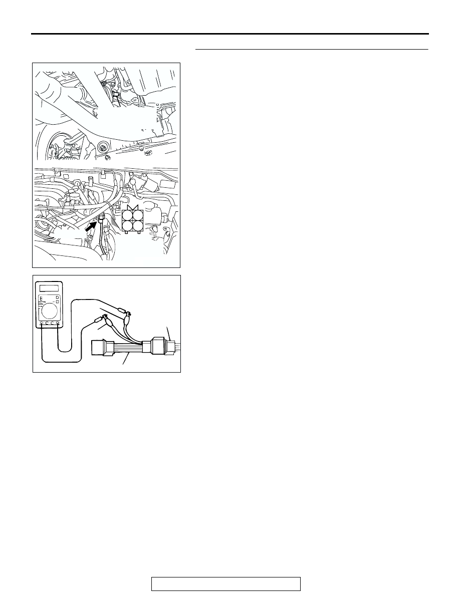
STEP 2. Check the left bank heated oxygen sensor (front).

(1) Disconnect left bank heated oxygen sensor (front) 

connector B-26 and connect test harness special tool, 
MB991316, to the connector on the left bank heated oxygen 
(front) sensor side.

(2) Measure the resistance between heated oxygen sensor 

connector terminal No. 1 (red clip) and terminal No. 3 (blue 
clip).

Standard value: 4.5 

 8.0 ohms [at 20°C (68°F)]

Q: Is the measured resistance between 4.5 and 8.0 ohms 

[at 20

°C (68°F)]?

YES : Go to Step 3.
NO :  Replace the left bank heated oxygen sensor (front). 

Then go to Step 12.

AK201278

1

2

3

4

CONNECTOR: B-26

B-26(GR)

AC

HARNESS 
CONNECTOR: 
COMPONENT 
SIDE

LEFT BANK
HEATED OXYGEN
SENSOR (FRONT)

AKX01624 AB

MB991316

HEATED
OXYGEN
SENSOR
EQUIPMENT
SIDE
CONNECTOR

BLUE

RED

MULTIPORT FUEL INJECTION (MFI) DIAGNOSIS

TSB Revision

MULTIPORT FUEL INJECTION (MFI)

13A-316

STEP 3. Measure the power supply voltage at left bank 
heated oxygen sensor (front) harness side connector B-26.

(1) Disconnect the connector B-26 and measure at the harness 

side.

(2) Turn the ignition switch to the "ON" position.

(3) Measure the voltage between terminal No. 1 and ground.

• Voltage should be battery positive voltage.

(4) Turn the ignition switch to the "LOCK" (OFF) position.
Q: Is battery positive voltage (approximately 12 volts) 

present?
YES : 
Go to Step 5.
NO :  Go to Step 4.

STEP 4. Check harness connector B-22X at the MFI relay 
for damage.

Q: Is the harness connector in good condition?

YES : Repair harness wire between MFI relay connector 

B-22X (terminal No. 1) and left bank heated oxygen 
sensor (front) connector B-26 (terminal No. 1) 
because of open circuit or short circuit to ground. 
Then go to Step 12.

NO :  Repair or replace it. Refer to GROUP 00E, Harness 

Connector Inspection 

P.00E-2

. Then go to Step 12. 

AK201278

1

2

3

4

CONNECTOR: B-26

B-26(GR)

AC

HARNESS 
CONNECTOR: 
COMPONENT 
SIDE

LEFT BANK
HEATED OXYGEN
SENSOR (FRONT)

AKX01496

B-26 HARNESS 
CONNECTOR: 
COMPONENT SIDE

1

2

3

4

AR

AK200951

2 1

3

4

B-22X

AB

CONNECTOR: B-22X

HARNESS 
CONNECTOR: 
COMPONENT SIDE

MULTIPORT FUEL INJECTION (MFI) DIAGNOSIS

TSB Revision

MULTIPORT FUEL INJECTION (MFI)

13A-317

STEP 5. Meaure the power supply voltage at PCM 
connector D-132 by backprobing.

(1) Do not disconnect the connector D-132.
(2) Turn the ignition switch to the "ON" position.

(3) Measure the voltage between terminal No. 10 and ground 

by backprobing.

• Voltage should be battery positive voltage.

(4) Turn the ignition switch to the "LOCK" (OFF) position.
Q: Is battery positive voltage (approximately 12 volts) 

present?
YES : 
Go to Step 8.
NO :  Go to Step 6.

STEP 6. Check harness connector D-132 at PCM for 
damage.

Q: Is the harness connector in good condition?

YES : Go to Step 7.
NO :  Repair or replace it. Refer to GROUP 00E, Harness 

Connector Inspection 

P.00E-2

. Then go to Step 12. 

AK200938

2

3

4

5

6

7

8

9

1

10

14

15

16

17

18

19

20

21

22

23

24

25

26

27

11

12

13

AB

CONNECTOR: D-132

HARNESS CONNECTOR: 
COMPONENT SIDE

PCM

D-132(GR)

AK201411

1

2

3

5

6 7 8 9

4

20

21 22

232425

2627

10111213

14 15

16 1718

19

D-132 HARNESS 
CONNECTOR: 
HARNESS SIDE

AB

AK200938

2

3

4

5

6

7

8

9

1

10

14

15

16

17

18

19

20

21

22

23

24

25

26

27

11

12

13

AB

CONNECTOR: D-132

HARNESS CONNECTOR: 
COMPONENT SIDE

PCM

D-132(GR)

MULTIPORT FUEL INJECTION (MFI) DIAGNOSIS

TSB Revision

MULTIPORT FUEL INJECTION (MFI)

13A-318

STEP 7. Check for open circuit or short circuit to ground 
between left bank heated oxygen sensor (front) connector 
B-26 (terminal No. 3) and PCM connector D-132 (terminal 
No. 10).

Q: Is the harness wire in good condition?

YES : Replace the PCM. Then go to Step 12. 
NO :  Repair it. Then go to Step 12.

AK201278

1

2

3

4

CONNECTOR: B-26

B-26(GR)

AC

HARNESS 
CONNECTOR: 
COMPONENT 
SIDE

LEFT BANK
HEATED OXYGEN
SENSOR (FRONT)

AK200938

2

3

4

5

6

7

8

9

1

10

14

15

16

17

18

19

20

21

22

23

24

25

26

27

11

12

13

AB

CONNECTOR: D-132

HARNESS CONNECTOR: 
COMPONENT SIDE

PCM

D-132(GR)


Content   ..  205  206  207  208   ..