Mitsubishi Montero (2004+). Manual - part 202


  Index      Mitsubishi     Mitsubishi Montero - service repair manual 2004 year


Search            


Content   ..  200  201  202  203   ..


Mitsubishi Montero (2004+). Manual - part 202


MULTIPORT FUEL INJECTION (MFI) DIAGNOSIS

TSB Revision

MULTIPORT FUEL INJECTION (MFI)

13A-295

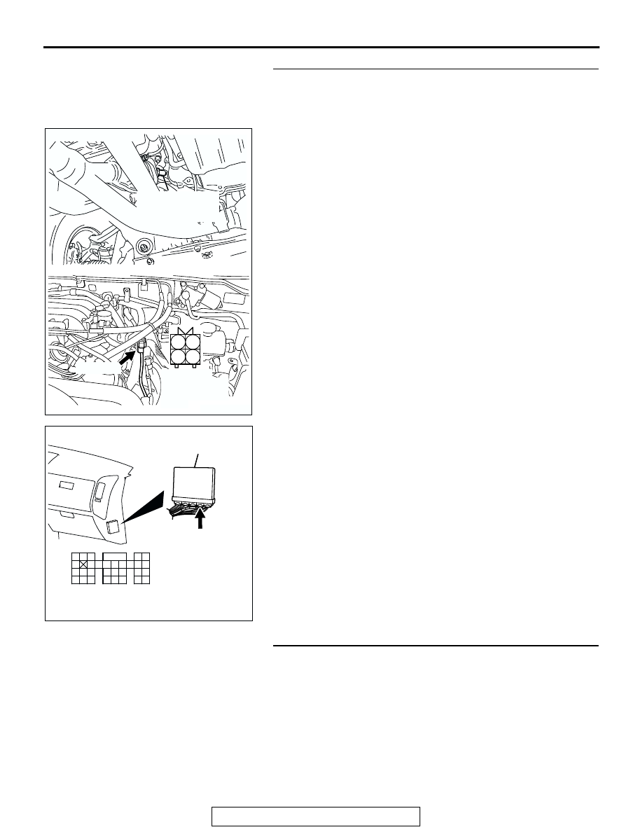
STEP 2. Check for short circuit to power supply between 
left bank heated oxygen sensor (front) connector B-26 
(terminal No. 4) and PCM connector D-135 (terminal No. 
108).

Q: Is the harness wire in good condition?

YES : Replace the PCM. Then go to Step 3.
NO :  Repair it. Then go to Step 3.

STEP 3. Perform the OBD-II drive cycle.
(1) Carry out a test drive with the drive cycle pattern. Refer to 

Diagnostic Function 

− OBD-II Drive Cycle − Procedure 6 − 

Other Monitor 

P.13A-4

.

(2) Check the diagnostic trouble code (DTC).
Q: Is DTC P0152 set?

YES : Repeat the troubleshooting.
NO :  The procedure is complete.

AK201278

1

2

3

4

CONNECTOR: B-26

B-26(GR)

AC

HARNESS 
CONNECTOR: 
COMPONENT 
SIDE

LEFT BANK
HEATED OXYGEN
SENSOR (FRONT)

AK200947

91

92

93

94

95

96

97

98

99

100

101

102

103

104

105

106

107

108

109

110

111

112

113

114

115

116

117

118

119

120

CONNECTOR: D-135

HARNESS CONNECTOR: 
COMPONENT SIDE

AB

PCM

D-135(GR)

MULTIPORT FUEL INJECTION (MFI) DIAGNOSIS

TSB Revision

MULTIPORT FUEL INJECTION (MFI)

13A-296

DTC P0153: Heated Oxygen Sensor Circuit Slow Response (bank 2, sensor 1)

BL

ACK

BL

ACK

BL

ACK

TO PCM

FROM MFI RELAY

WHITE

AK201135

96

108

4

3

1

LEFT BANK
HEATED OXYGEN
SENSOR (FRONT)

POWERTRAIN CONTROL
MODULE (PCM)

11

9

7

2

4

3

1 2

B-26

MU802665

1

12

23 24 25 26

2

13

3

14

4

15

5

16

6

17

7

18

8

19

9

20 21 22

27 28 29 30 31 32 33

10 11

D-116

1
5

7 8

3 4
9 10

2
6

D-14

MU801335

Left Bank Heated Oxygen Sensor (front) Circuit

9192

939495

96979899

100

105

113114

115116117

118119120

106

107108109

110111112

101102103

104

D-135

(MU803805)

AK201277

CONNECTOR: B-26

B-26(GR)

AD

LEFT BANK
HEATED OXYGEN
SENSOR (FRONT)

AK201038AF

CONNECTOR: D-135

PCM

D-135(GR)

AK200949

3

4

7

8

1

2

5

6

B-44(B)

CONNECTOR: B-44

AB

HARNESS 
CONNECTOR: 
COMPONENT SIDE

MULTIPORT FUEL INJECTION (MFI) DIAGNOSIS

TSB Revision

MULTIPORT FUEL INJECTION (MFI)

13A-297

.

CIRCUIT OPERATION

• A voltage corresponding to the oxygen concen-

tration in the exhaust gas is sent to the PCM (ter-
minal No. 108) from the output terminal (terminal 
No. 4) of the left bank heated oxygen sensor 
(front).

• Terminal No. 2 of the left bank heated oxygen 

sensor (front) is grounded with PCM (terminal 
No. 96).

.

TECHNICAL DESCRIPTION

• The left bank heated oxygen sensor (front) 

detects the concentration of oxygen in the 
exhaust gas; it converts those data to voltage, 
and inputs the resulting signals to the PCM.

• When the left bank heated oxygen sensor (front) 

begins to deteriorate, the left bank heated oxygen 
sensor signal response becomes poor.

• The PCM forcibly varies the air/fuel mixture to 

make it leaner and richer, and checks the 
response speed of the left bank heated oxygen 
sensor (front). In addition, the PCM also checks 
for an open circuit in the left bank heated oxygen 
sensor (front) output line.

.

DESCRIPTIONS OF MONITOR METHODS
Left bank heated oxygen sensor (front) rich/lean 

switching frequency is under specified value.

.

MONITOR EXECUTION
Continuous

.

MONITOR EXECUTION CONDITIONS (Other 
monitor and Sensor)

Other Monitor (There is no temporary DTC stored 

in memory for the item monitored below)

• Heated oxygen sensor heater (front) monitor

• Misfire monitor

• Fuel system monitor

Sensor (The sensor below is determined to be 

normal)

• Volume airflow sensor

• Engine coolant temperature sensor

• Intake air temperature sensor

• Barometric pressure sensor

• Throttle position sensor

• Accelerator pedal position sensor

.

AK201049

CONNECTOR: D-116

D-116

AC

MULTIPORT FUEL INJECTION (MFI) DIAGNOSIS

TSB Revision

MULTIPORT FUEL INJECTION (MFI)

13A-298

DTC SET CONDITIONS

Logic Flow Chart

.

Check Conditions

• Engine coolant temperature is higher than 50°C 

(122

°F).

• Engine speed is between 1,250 and 3,000 r/min.

• Volumetric efficiency is between 24 and 65 per-

cent.

• Under the closed loop air/fuel control.

• The accelerator pedal is not closed.

• Short-term fuel trim is at between −30 and +25 

percent.

• More than 3 seconds have elapsed after the 

abovementioned conditions have been met.

• The PCM monitors for this condition for 7 cycles 

of 12 seconds each during the drive cycle.

Judgment Criteria

• The left bank heated oxygen sensor (front) sends 

"lean" and "rich" signals alternately 11 times or 
less for 12 seconds.

NOTE: If the sensor switching frequency is lower 
than the Judgment Criteria due to the MUT-III OBD-II 
test Mode 

 H02S Test Results, it is assumed that 

the heated oxygen sensor has deteriorated. If it is 
higher, it is assumed that the harness is damaged or 
has a short circuit.
If the heated oxygen sensor signal voltage has not 
changed even once (lean/rich) after the DTC was 
erased, the sensor switch time will display as 0 sec-
onds.

.

OBD-II DRIVE CYCLE PATTERN
Refer to Diagnostic Function 

− OBD-II Drive Cycle − 

Procedure 4 

− Heated Oxygen Sensor Monitor 

P.13A-4

.

.

TROUBLESHOOTING HINTS (The most likely 
causes for this code to be set are: )

• Left bank heated oxygen sensor (front) deterio-

rated.

• Connector damage.

F1: THRESHOLD VALUE FOR REAL-TIME SWITDHING FREQUENCY
F0: THRESHOLD VALUE FOR AVERAGE SWITDHING FREQUENCY

START

MONITORING

CONDITIONS

MALFUNCTION

GOOD

END

NO

NO

YES

YES

Ff < F0

CALCULATE AVERAGE SWITCHING

FREQUENCY (Ff) OVER SPECIFIED TIMES

AK302932


Content   ..  200  201  202  203   ..