Mitsubishi Montero (2004+). Manual - part 165


  Index      Mitsubishi     Mitsubishi Montero - service repair manual 2004 year


Search            


Content   ..  163  164  165  166   ..


Mitsubishi Montero (2004+). Manual - part 165


MULTIPORT FUEL INJECTION (MFI) DIAGNOSIS

TSB Revision

MULTIPORT FUEL INJECTION (MFI)

13A-147

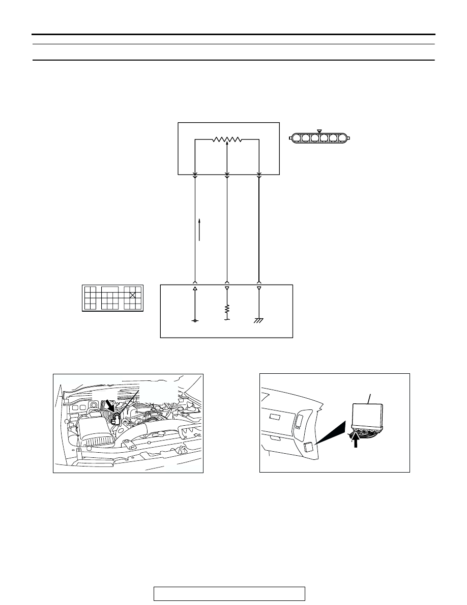
DTC P0123: Throttle Position Sensor (Main) Circuit high Input

.

CIRCUIT OPERATION

• A 5-volt power supply is applied on the throttle 

position sensor (main) power terminal (terminal 
No. 2) from the PCM (terminal No. 106).
The ground terminal (terminal No. 4) is grounded 
with PCM (terminal No. 105).

• When the throttle valve shaft is turned from the 

idle position to the fully opened position, the 
resistance between the throttle position sensor 
(main) output terminal (terminal No. 1) and 
ground terminal (terminal No. 4) will increase 
according to the rotation.

.

AK201130

RED

WHITE

BLA

CK

B-05

5 V

106

2

THROTTLE
POSITION
SENSOR
(MAIN)

POWERTRAIN CONTROL MODULE (PCM)

115

105

1

4

Throttle Position Sensor (Main) Circuit

9192

939495

96979899

100

105

113114

115116117

118119120

106

107108109

110111112

101102103

104

D-135

(MU803805)

6

1 2 3 4 5

AK201173

THROTTLE 
POSITION 
SENSOR

AB

B-05(B)

CONNECTOR: B-05

AK201038

CONNECTOR: D-132

AB

PCM

D-132(GR)

MULTIPORT FUEL INJECTION (MFI) DIAGNOSIS

TSB Revision

MULTIPORT FUEL INJECTION (MFI)

13A-148

TECHNICAL DESCRIPTION

• The throttle position sensor (main) outputs volt-

age which corresponds to the throttle valve open-
ing angle.

• The PCM checks whether the voltage is within a 

specified range.

.

DESCRIPTIONS OF MONITOR METHODS
Throttle position sensor (main) output voltage is out 

of specified range.

.

MONITOR EXECUTION
Continuous

.

MONITOR EXECUTION CONDITIONS (Other 
monitor and Sensor)

Other Monitor (There is no temporary DTC stored 

in memory for the item monitored below)

• Not applicable

Sensor (The sensor below is determined to be 

normal)

• Not applicable

.

DTC SET CONDITIONS

Logic Flow Chart

.

Check Conditions

• Ignition switch "ON" position.

Judgement Criteria

• Throttle position sensor (main) output voltage 

should be 4.8 volts or more for 0.5 second.

START

YES

YES

YES

NO

NO

NO

CONTINUOUS

FAILURE FOR 0.5sec

MALFUNCTION

END

GOOD

OUTPUT VOLTAGE

< =0.35V

OUTPUT VOLTAGE > =4.8V

AK302926

MULTIPORT FUEL INJECTION (MFI) DIAGNOSIS

TSB Revision

MULTIPORT FUEL INJECTION (MFI)

13A-149

.

OBD-II DRIVE CYCLE PATTERN
None.

.

TROUBLESHOOTING HINTS (The most likely 
causes for this code to be set are:)

• Throttle position sensor failed.

• Open throttle position sensor (main) circuit, har-

ness damage, or connector damage.

• PCM failed.

DIAGNOSIS

Required Special Tools:

• MB991958: Scan Tool (MUT-III Sub Assembly)

• MB991824: V.C.I.

• MB991827: USB Cable

• MB991911: Main Harness B

• MB991658: Test Harness Set

STEP 1. Using scan tool MB991958, check data list item 79: 
Throttle Position Sensor (main).

CAUTION

To prevent damage to scan tool MB991958, always turn the 
ignition switch to the "LOCK"(OFF) position before con-
necting or disconnecting scan tool MB991958.
(1) Connect scan tool MB991958 to the data link connector.
(2) Turn the ignition switch to the "ON" position.
(3) Detach the intake air hose at the throttle body.
(4) Disconnect the connector of the throttle position sensor.
(5) Use test harness special tool (MB991658) to connect only 

terminals No. 1, No. 2, No. 3, and No. 4.

(6) Set scan tool MB991958 to the data reading mode for item 

79, Throttle Position Sensor (main).

• Output voltage should be between 0.3 and 0.7 volt when 

the throttle valve is fully closed with your finger.

• Output voltage should be 4.0 volts or more when the 

throttle valve is fully open with your finger.

(7) Turn the ignition switch to the "LOCK"(OFF) position.
Q: Is the sensor operating properly?

YES : It can be assumed that this malfunction is intermittent. 

Refer to GROUP 00, How to Use 
Troubleshooting/Inspection Service Points 

P.00-6

.

NO :  Go to Step 2.

STEP 2. Check harness connector B-05 at throttle position 
sensor for damage.
Q: Is the harness connector in good condition?

YES : Go to Step 3.
NO :  Repair or replace it. Refer to GROUP 00E, Harness 

Connector Inspection 

P.00E-2

. Then go to Step 8.

AK302970

AB

MB991911

MB991824

MB991827

AK201174

1

6 5 4 3 2

B-05(B)

CONNECTOR: B-05

HARNESS 
CONNECTOR: 
COMPONENT SIDE

AB

MULTIPORT FUEL INJECTION (MFI) DIAGNOSIS

TSB Revision

MULTIPORT FUEL INJECTION (MFI)

13A-150

STEP 3. Check the continuity at throttle position sensor 
harness side connector B-05.
(1) Disconnect the connector B-05 and measure at the harness 

side.

(2) Measure the continuity between terminal No. 4 and ground

• Should be less than 2 ohms.

Q: Dose continuity exist?

YES : Go to Step 7.
NO :  Go to Step 4.

STEP 4. Check harness connector D-135 at PCM for 
damage.
Q: Is the harness connector in good condition?

YES : Go to Step 5.
NO :  Repair or replace it. Refer to GROUP 00E, Harness 

Connector Inspection 

P.00E-2

. Then go to Step 8.

AK201174

1

6 5 4 3 2

B-05(B)

CONNECTOR: B-05

HARNESS 
CONNECTOR: 
COMPONENT SIDE

AB

AK201446

1

6 5 4 3 2

AB

B-05 HARNESS 
CONNECTOR: 
COMPONENT SIDE

AK200947

91

92

93

94

95

96

97

98

99

100

101

102

103

104

105

106

107

108

109

110

111

112

113

114

115

116

117

118

119

120

CONNECTOR: D-135

HARNESS CONNECTOR: 
COMPONENT SIDE

AB

PCM

D-135(GR)


Content   ..  163  164  165  166   ..