Mitsubishi Montero (2004+). Manual - part 159


  Index      Mitsubishi     Mitsubishi Montero - service repair manual 2004 year


Search            


Content   ..  157  158  159  160   ..


Mitsubishi Montero (2004+). Manual - part 159


MULTIPORT FUEL INJECTION (MFI) DIAGNOSIS

TSB Revision

MULTIPORT FUEL INJECTION (MFI)

13A-123

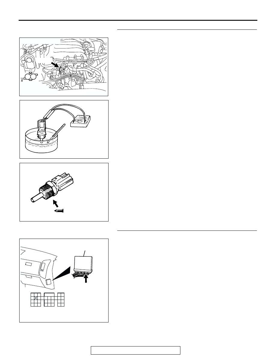
STEP 11. Check the engine coolant temperature sensor.
(1) Disconnect the engine coolant temperature sensor 

connector B-37.

(2) Remove the engine coolant temperature sensor.

(3) With the temperature sensing portion of engine coolant 

temperature sensor immersed in hot water, check 
resistance.

Standard value:

14 

 17 k [at 20°C (4°F)]

5.1 

 6.5 k [at 0°C (32°F)]

2.1 

 2.7 k [at 20°C (68°F)]

0.9 

 1.3 k [at 40°C (104°F)]

0.48 

 0.68k [at 60°C (140°F)]

0.26 

 0.36 k [at 80°C (176°F)]

(4) Apply 3M

 AAD part number 8731 or equivalent on the 

screw section of the engine coolant temperature sensor.

(5) Install the engine coolant temperature sensor, and tighten 

to the specified torque.

Tightening torque: 29 

± 10 Nm (22 ± 7 ft-lb)

Q: Is the resistance at the standard value?

YES : Go to Step 12.
NO :  Replace the engine coolant temperature sensor. Then 

go to Step 14.

STEP 12. Check connector D-135 at PCM for damage.
Q: Is the connector in good condition?

YES : Go to Step 13.
NO :  Repair or replace it. Refer to GROUP 00E, Harness 

Connector Inspection 

P.00E-2

. Then go to Step 14.

AK200943

1

2

AB

HARNESS 
CONNECTOR: 
COMPONENT SIDE

CONNECTOR: B-37

B-37(B)

AKX01622

AKX01623 AB

AK200947

91

92

93

94

95

96

97

98

99

100

101

102

103

104

105

106

107

108

109

110

111

112

113

114

115

116

117

118

119

120

CONNECTOR: D-135

HARNESS CONNECTOR: 
COMPONENT SIDE

AB

PCM

D-135(GR)

MULTIPORT FUEL INJECTION (MFI) DIAGNOSIS

TSB Revision

MULTIPORT FUEL INJECTION (MFI)

13A-124

STEP 13. Check for harness damage between engine 
coolant temperature sensor connector B-37 (terminal No. 
1) and PCM connector D-135 (terminal No. 98).
Q: Is the harness wire in good condition?

YES : Replace the PCM. Then go to Step 14.
NO :  Repair it. Then go to Step 14.

STEP 14. Test the OBD-II drive cycle.
(1) Carry out a test drive with the drive cycle pattern. Refer to 

Diagnostic Function 

− OBD-II Drive Cycle − Procedure 6 − 

Other Monitor 

P.13A-4

.

(2) Check the diagnostic trouble code (DTC).
Q: Is DTC P116 set?

YES : Retry the troubleshooting.
NO :  The inspection is complete.

AK200943

1

2

AB

HARNESS 
CONNECTOR: 
COMPONENT SIDE

CONNECTOR: B-37

B-37(B)

AK200947

91

92

93

94

95

96

97

98

99

100

101

102

103

104

105

106

107

108

109

110

111

112

113

114

115

116

117

118

119

120

CONNECTOR: D-135

HARNESS CONNECTOR: 
COMPONENT SIDE

AB

PCM

D-135(GR)

MULTIPORT FUEL INJECTION (MFI) DIAGNOSIS

TSB Revision

MULTIPORT FUEL INJECTION (MFI)

13A-125

DTC P0117: Engine Coolant Temperature Circuit Low Input

.

CIRCUIT OPERATION

• 5-volt voltage is applied to the engine coolant 

temperature sensor output terminal (terminal No. 
1) from the PCM (terminal No. 98) via the resistor 
in the PCM. The ground terminal (terminal No. 2) 
is grounded with PCM (terminal No. 96).

• The engine coolant temperature sensor is a neg-

ative temperature coefficient type of resistor. It 
has the characteristic that when the engine cool-
ant temperature rises the resistance decreases.

• The engine coolant temperature sensor output 

voltage increases when the resistance increases 
and decreases when the resistance decreases.

.

YELLO

W

-GREEN

BLA

C

K

AK302923

ENGINE COOLANT
TEMPERATURE SENSOR

POWERTRAIN CONTROL MODULE(PCM)

5 V

98

2

B-37

(MU802406)

96

1

Engine Coolant Temperature Sensor Circuit

1 2

9192

939495

96979899

100

105

113114

115116117

118119120

106

107108109

110111112

101102103

104

D-135

(MU803805)

AK200942

ENGINE COOLANT
TEMPERATURE SENSOR

AK200942AB

B-37(B)

CONNECTOR: B-37

AK201038AF

CONNECTOR: D-135

PCM

D-135(GR)

MULTIPORT FUEL INJECTION (MFI) DIAGNOSIS

TSB Revision

MULTIPORT FUEL INJECTION (MFI)

13A-126

TECHNICAL DESCRIPTION

• The engine coolant temperature sensor converts 

the engine coolant temperature to a voltage and 
outputs it.

• The PCM checks whether this voltage is within a 

specified range.

.

DESCRIPTIONS OF MONITOR METHODS
Engine coolant temperature sensor output voltage is 

out of specified range.

.

MONITOR EXECUTION
Continuous

.

MONITOR EXECUTION CONDITIONS (Other 
monitor and Sensor)

Other Monitor (There is no temporary DTC stored 

in memory for the item monitored below)

• Not applicable

Sensor (The sensor below is determined to be 

normal)

• Not applicable

.

DTC SET CONDITIONS

Logic Flow Chart

Check Conditions

• 2 seconds or more have passed since the engine 

starting sequence was completed.

START

OUTPUT VOLTAGE > 4.6V

OUTPUT VOLTAGE < 0.1V

END

NO

NO

NO

YES

YES

YES

MALFUNCTION

GOOD

CONTINUOUS

FAILURE FOR 2secs

MONITORING

CONDITIONS?

NO

YES

AK302925


Content   ..  157  158  159  160   ..