Mitsubishi Montero (2004+). Manual - part 149


  Index      Mitsubishi     Mitsubishi Montero - service repair manual 2004 year


Search            


Content   ..  147  148  149  150   ..


Mitsubishi Montero (2004+). Manual - part 149


MULTIPORT FUEL INJECTION (MFI) DIAGNOSIS

TSB Revision

MULTIPORT FUEL INJECTION (MFI)

13A-83

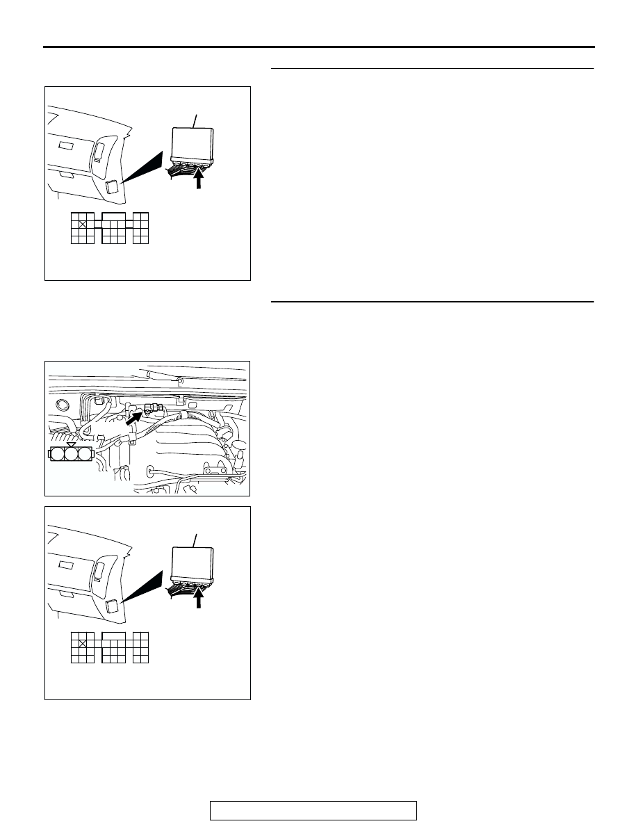
STEP 16. Check connector D-135 at PCM for damage.
Q: Is the connector in good condition?

YES : Go to Step 17.
NO :  Repair or replace it. Refer to GROUP 00E, Harness 

Connector Inspection 

P.00E-2

. Then go to Step 18.

STEP 17. Check for short circuit to ground and harness 
damage between manifold absolute pressure sensor 
connector B-28 (terminal No. 1) and PCM connector D-135 
(terminal No. 101).
Q: Is the harness wire in good condition?

YES : Replace the manifold absolute pressure sensor. Then 

go to Step 18.

NO :  Repair it. Then go to Step 18.

AK200947

91

92

93

94

95

96

97

98

99

100

101

102

103

104

105

106

107

108

109

110

111

112

113

114

115

116

117

118

119

120

CONNECTOR: D-135

HARNESS CONNECTOR: 
COMPONENT SIDE

AB

PCM

D-135(GR)

AK200975

1

2

3

AB

HARNESS 
CONNECTOR: 
COMPONENT SIDE

CONNECTOR: B-28

B-28(B)

AK200947

91

92

93

94

95

96

97

98

99

100

101

102

103

104

105

106

107

108

109

110

111

112

113

114

115

116

117

118

119

120

CONNECTOR: D-135

HARNESS CONNECTOR: 
COMPONENT SIDE

AB

PCM

D-135(GR)

MULTIPORT FUEL INJECTION (MFI) DIAGNOSIS

TSB Revision

MULTIPORT FUEL INJECTION (MFI)

13A-84

STEP 18. Test the OBD-II drive cycle.
(1) Carry out a test drive with the drive cycle pattern. Refer to  

Diagnostic Function 

− OBD-II Drive Cycle − Procedure 6 − 

Other Monitor 

P.13A-4

.

(2) Check the diagnostic trouble code (DTC).
Q: Is DTC P0107 set?

YES : Retry the troubleshooting.
NO :  The inspection is complete.

DTC P0108: Manifold Absolute Pressure Circuit High Input

AK302421

GREEN-YELLO

W

BLUE-YELLO

W

BLA

CK

POWERTRAIN CONTROL 
MODULE (PCM)

5V

B-28

(MU802723)

MANIFOLD ABSOLUTE 
PRESSURE SENSOR

3

1

2

Manifold Absolute Pressure Sensor Circuit

97

96

101

1

2

3

9192

939495

96979899

100

105

113114

115116117

118119120

106

107108109

110111112

101102103

104

D-135

(MU803805)

MULTIPORT FUEL INJECTION (MFI) DIAGNOSIS

TSB Revision

MULTIPORT FUEL INJECTION (MFI)

13A-85

.

CIRCUIT OPERATION

• A 5-volt voltage is supplied to the manifold abso-

lute pressure sensor power terminal (terminal No. 
3) from PCM (terminal No. 97). The ground termi-
nal (terminal No. 2) is grounded with PCM (termi-
nal No. 96).

• A voltage that is proportional to the intake mani-

fold pressure is sent to the PCM (terminal No. 
101) from the manifold absolute pressure sensor 
output terminal (terminal No. 1).

.

TECHNICAL DESCRIPTION

• The manifold absolute pressure sensor outputs a 

voltage which corresponds to the intake manifold 
pressure.

• The PCM checks whether this voltage is within a 

specified range.

.

DESCRIPTIONS OF MONITOR METHODS
Manifold absolute pressure sensor output voltage is 

out of specified range.

.

MONITOR EXECUTION
Continuous

.

MONITOR EXECUTION CONDITIONS (Other 
monitor and Sensor)

Other Monitor (There is no temporary DTC stored 

in memory for the item monitored below)

• Not applicable

Sensor (The sensor below is determined to be 

normal)

• Not applicable

.

AK200974

MANIFOLD 
ABSOLUTE
PRESSURE 
SENSOR

AD

B-28(B)

CONNECTOR: B-28

AK201038AF

CONNECTOR: D-135

PCM

D-135(GR)

MULTIPORT FUEL INJECTION (MFI) DIAGNOSIS

TSB Revision

MULTIPORT FUEL INJECTION (MFI)

13A-86

DTC SET CONDITIONS

Logic Flow Chart

Check Conditions

• 8 minutes or more have passed since the starting 

sequence was completed, when the engine cool-
ant temperature at engine start is 0

°C (32°F) or 

lower.

Judgement Criteria

• Manifold Absolute pressure is 117 kPa (34.6 

in.Hg) or higher for 2 seconds.

.

OBD-II DRIVE CYCLE PATTERN
Refer to Diagnostic Function 

− OBD-II Drive Cycle − 

Procedure 6 

− Other Monitor 

P.13A-4

.

.

TROUBLESHOOTING HINTS (The most likely 
causes for this code to be set are: )

• Manifold Absolute pressure sensor failed.

• Open manifold absolute pressure sensor circuit, 

or connector damage.

• PCM failed.

YES

YES

YES

YES

NO

NO

NO

NO

MONITORING

CONDITIONS

PRESSURE < 5.0kPa (1.4in.Hg)

PRESSURE > 117kPa (34.6in.Hg)

CONTINUOUS

FAILURE FOR 2secs

MALFUNCTION

END

GOOD

START

AK302688


Content   ..  147  148  149  150   ..