Content .. 1218 1219 1220 1221 ..
Mitsubishi Montero (2004+). Manual - part 1220
SRS CONTROL UNIT (SRS-ECU)
TSB Revision
SUPPLEMENTAL RESTRAINT SYSTEM (SRS)
52B-215
SRS CONTROL UNIT (SRS-ECU)
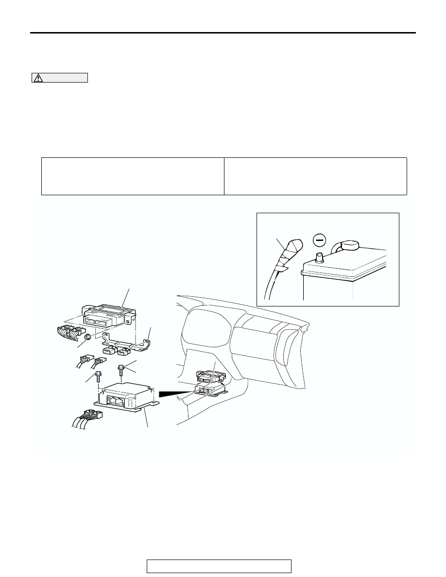
REMOVAL AND INSTALLATION
M1524002100446
WARNING
•
Never attempt to disassemble or repair the SRS-ECU. If faulty, replace it.
•
Do not drop or subject the SRS-ECU to impact or vibration. If denting, cracking, deforma-
tion, or rust are discovered in the SRS-ECU, replace it with a new SRS-ECU.
•
After deployment of an air bag, replace the SRS-ECU with a new one.
•
Never use an ohmmeter on or near the SRS-ECU, and use only the special test equipment
described on
Pre-removal Operation
• Turn the ignition key to the "LOCK"(OFF) position.
• Front Floor Console Removal (Refer to GROUP 52A,
Floor Console
Post-installation Operation
• Front Floor Console Installation (Refer to GROUP 52A,
ACX01413
ACX00583
AC
2
3
4
5
4.9 ± 1.0 N·m
43 ± 8 in-lb
4.9 ± 1.0 N·m
43 ± 8 in-lb
4.9 ± 1.0 N·m
43 ± 8 in-lb
1
REMOVAL STEPS
<<A>>
1.
NEGATIVE (
−) BATTERY CABLE
CONNECTION
2.
TRANSFER-ECU
3.
CONNECTOR BRACKET
4.
BRACKET MOUNTING BOLT
(GROUNDING BOLT)
5.
SRS-ECU
INSTALLATION STEPS
>>A<<
5.
SRS-ECU
>>B<<
4.
BRACKET MOUNTING BOLT
(GROUNDING BOLT)
3.
CONNECTOR BRACKET
2.
TRANSFER-ECU
1.
NEGATIVE (-) BATTERY CABLE
CONNECTION
>>C<<
•
POST-INSTALLATION
INSPECTION