Mitsubishi Montero (2004+). Manual - part 122


  Index      Mitsubishi     Mitsubishi Montero - service repair manual 2004 year


Search            


Content   ..  120  121  122  123   ..


Mitsubishi Montero (2004+). Manual - part 122


PISTON AND CONNECTING ROD

TSB Revision

ENGINE OVERHAUL

11B-47

2. Before installation of each nut, apply engine oil to the 

threaded portion and bearing surface of the nut.

3. Loosely tighten each nut to the bolt.
4. Then tighten the nuts alternately to a torque of 27 

± 2 N⋅m 

(20 

± 1 ft-lb) to install the cap properly.

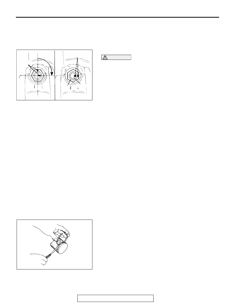
5. Make a paint mark on the head of each nut.

CAUTION

• If the nut is turned less than 90 degrees proper fasten-

ing performance may not be achieved. Be careful to 
tighten the nut exactly 90 degrees.

• If the nut is overtightened (exceeding 94 degrees), 

loosen the nut completely and then retighten it by 
repeating the tightening procedure from step 3.

6. Make a paint mark on the bolt end at a position 90 degrees  

to 94 degrees from the paint mark made on the nut in the 
direction of tightening the nut.

7. Turn the nut another 90 to 94 degrees and make sure that 

the paint marks on the nut and bolt are aligned.

INSPECTION

M1113008500439

.

PISTON
Replace the piston if scratches or seizure is evident on its sur-
faces (especially the thrust surface). Replace the piston if it is 
cracked.

.

PISTON PIN
1. Insert the piston pin into the piston pin hole with a thumb. 

You should feel a slight resistance. Replace the piston pin if 
it can be easily inserted or there is excessive play.

2. The piston and piston pin must be replaced as an assembly.

.

PISTON RING 
1. Check the piston ring for damage, excessive wear, and 

breakage and replace if defects are evident. If the piston has 
been replaced with a new one, the piston rings must also be 
replaced with new ones.

2. Check for clearance between the piston ring and ring 

groove. If the limit is exceeded, replace the ring or piston, or 
both.

Standard value:

Number 1: 0.03 

 0.07 mm (0.0012  0.0027 inch)

Number 2: 0.02 

 0.06 mm (0.0008  0.0023 inch)

Limit: 0.1 mm (0.003 inch)

AKX01401AB

90˚ to 94˚

PAINT

MARKS

NUT

BOLT

PAINT

MARKS

AKX00612

PISTON AND CONNECTING ROD

TSB Revision

ENGINE OVERHAUL

11B-48

3. Insert the piston ring into the cylinder bore. Force the ring 

down with a piston, the piston crown being in contact with 
the ring, to correctly position it at right angles to the cylinder 
wall. Then, measure the end gap with a feeler gauge.
If the ring gap is excessive, replace the piston ring.

Standard value:

Number 1: 0.25 

 0.40 mm (0.010  0.016 inch)

Number 2: 0.35 

 0.50 mm (0.014  0.020 inch)

Oil: 0.10 

 0.35 mm (0.004  0.014 inch)

Limit:

Number 1, Number 2: 0.8 mm (0.03 inch)
Oil: 1.0 mm (0.03 inch)

.

CRANKSHAFT PIN OIL CLEARANCE 
<PLASTIC GAUGING MATERIAL METHOD>
The crankshaft oil clearance can be measured easily by using 
plastic gauging material, as follows:
1. Remove oil from the crankshaft pin and the bearing inner 

surface.

2. Cut plastic gauging material to the same length as the width 

of the bearing and place it on the pin in parallel with its axis.

3. Install the connecting rod cap carefully and tighten the nuts 

to the specified torque.

4. Carefully remove the connecting rod cap.
5. Measure the width of the smashed plastic gauging material 

at its widest section by using a scale printed on the plastic 
gauging material bag.

Standard value: 0.02 

 0.04 mm (0.0008  0.0016 inch)

Limit: 0.1 mm (0.003 inch)

AKX00719

PUSH IN BY
PISTON

PISTON
RING GAP

PISTON RING

AB

AKX00731AB

SCALE

CRANKSHAFT AND CYLINDER BLOCK

TSB Revision

ENGINE OVERHAUL

11B-49

CRANKSHAFT AND  CYLINDER BLOCK

REMOVAL AND INSTALLATION

M1113008700596

Required Special Tool:

• MD998718: Crankshaft Rear Oil Seal Installer

AK201082 AB

1

2

3

4

5

6

14

15

16

13

12

11

10

9

8

23 ± 2 N·m
17 ± 1 ft-lb

74 ± 4 N·m
54 ± 3 ft-lb

74 ± 2 N·m
54 ± 1 ft-lb

28 ± 2 N·m
21 ± 1 ft-lb

11 ± 1 N·m
97 ± 9 in-lb

11 ± 1 N·m
97 ± 9 in-lb

APPLY ENGINE OIL
TO ALL MOVING
PARTS BEFORE
INSTALLTION.

7

9 ± 2 N·m
79 ± 18 in-lb

REMOVAL STEPS

1. ADAPTER PLATE
2. DRIVE PLATE
3. CRANKSHAFT ADAPTOR
4. REAR PLATE

>>F<<

5. OIL SEAL CASE 

>>E<<

6. CRANKSHAFT REAR OIL SEAL
7. BAFFLE PLATE

>>D<<

8. BEARING CAP BOLT

>>D<<

9. BEARING CAP

>>B<<

10. CRANKSHAFT BEARING, LOWER
11. CRANKSHAFT

>>C<<

12. THRUST BEARING

>>B<<

13. CRANKSHAFT BEARING, UPPER
14. KNOCK SENSOR

>>A<<

15. KNOCK SENSOR BRACKET
16. CYLINDER BLOCK

REMOVAL STEPS (Continued)

CRANKSHAFT AND CYLINDER BLOCK

TSB Revision

ENGINE OVERHAUL

11B-50

INSTALLATION SERVICE POINTS

.

>>A<< KNOCK SENSOR BRACKET INSTALLATION
Check that the bracket is in proper contact with the cylinder 
block boss and tighten to the specified torque in the order 
shown.

Tightening torque: 28 

± 2 Nm (21 ± 1 ft-lb)

.

>>B<< CRANKSHAFT BEARING INSTALLATION
1. Measure the crankshaft journal diameter and confirm its 

classification from the following table. In the case of a 
crankshaft supplied as a service part, identification 
colors/marks of its journals are painted/stamped at the 
positions shown in the illustration.

2. The cylinder block bearing bore diameter identification 

marks are stamped at the position shown in the illustration 
from left to right, beginning at No.1.

AKX00649

TIMING BELT SIDE

AB

1

2

3

4

AKX01391

No.4 JOURNAL

No.1 JOURNAL

No.2 JOURNAL

No.3 JOURNAL

LOCATION OF IDENTIFCATION COLOR

AB

AKX00648

BEARING BORE 
DIAMETER 
IDENTIFICATION
MARK

CYLINDER INSIDE 
DIAMETER SIZE MARK

TIMING BELT SIDE

AB

No.4

No.2

No.3

No.1

CRANKSHAFT JOURNAL OUTSIDE 
DIAMETER

CYLINDER BLOCK 
BEARING BORE

CRANKSHAFT 
BEARING No.1, 4

CRANKSHAFT 
BEARING No.2, 3

IDENTIFICATION 
COLOR

SIZE   mm (in)

IDENTIFICATION 
MARK

IDENTIFICATION 
COLOR

IDENTIFICATION 
COLOR

Yellow

63.994 

− 64.000

(2.5194 

− 2.5197)

I

Pink

Blue

II

Red

Pink

III

Green

Red

None

63.988 

− 63.994

(2.5192 

− 2.5194)

I

Red

Pink

II

Green

Red

III

Black

Green


Content   ..  120  121  122  123   ..