Mitsubishi Montero (2004+). Manual - part 1211


  Index      Mitsubishi     Mitsubishi Montero - service repair manual 2004 year


Search            


Content   ..  1209  1210  1211  1212   ..


Mitsubishi Montero (2004+). Manual - part 1211


SRS AIR BAG DIAGNOSIS

TSB Revision

SUPPLEMENTAL RESTRAINT SYSTEM (SRS)

52B-179

TROUBLESHOOTING HINTS

• Damaged wiring harnesses or connectors

• Short to the power supply in the left hand side-air-

bag module (squib) harness

• Malfunction of the SRS-ECU

.

DIAGNOSIS

Required Special Tools:

• MB991958: Scan Tool (MUT-III Sub Assembly)

• MB991824: Vehicle Communication Interface (V.C.I.)

• MB991827: MUT-III USB Cable

• MB991911: MUT-III Main Harness B (Vehicles without 

CAN communication system)

• MB991865: Dummy resister

• MB991866: Resister harness

STEP1. Check the side-airbag module (LH). (Using scan 
tool MB991958, read the diagnostic trouble code).
(1) Disconnect the negative battery terminal.
(2) Disconnect the left hand side-airbag connector F-15.

(3) Connect special tool MB991865 to special tool MB991866.

CAUTION

Do not insert a test probe into the terminal from its front 
side directly as the connector contact pressure may be 
weakened.
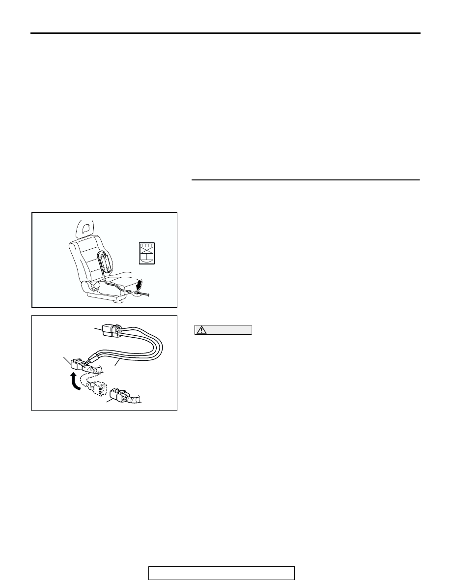
(4) Insert special tool MB991866 into the F-15 harness 

connector by backprobing.

(5) Connect the negative battery terminal.
(6) Erase the diagnostic trouble code memory, and check the 

diagnostic trouble code.

Q:  Is DTC 85 set?

YES : Go to Step 2.
NO :  Replace the seat back assembly of the front seat (LH) 

(Refer to GROUP 52A, Front Seat 

P.52A-14

). Then 

go to Step 4.

AC204635 AD

CONNECTOR: F-15

F-15 (R)

1 2

HARNESS SIDE 
CONNECTOR
(REAR VIEW)

AC006042 AX

MB991866
(RESISTOR HARNESS)

F-15 HARNESS 
CONNECTOR

F-15 SIDE-AIRBAG 
MODULE (LH) CONNECTOR

MB991865 (DUMMY 
RESISTOR: 3 

Ω)

SRS AIR BAG DIAGNOSIS

TSB Revision

SUPPLEMENTAL RESTRAINT SYSTEM (SRS)

52B-180

STEP 2. Check the side-airbag module (LH) circuit at the 
SRS-ECU connector E-07.
(1) Disconnect SRS-ECU connector E-07.

DANGER

To prevents the air bag from deploying unintention-
ally, disconnect the side-airbag module (LH) connec-
tor F-15 to short the squib circuit.

(2) Disconnect left hand side-airbag module connector F-15.
(3) Turn the ignition switch to the "ON" position.

CAUTION

Do not insert a test probe into the terminal from its front 
side directly as the connector contact pressure may be 
weakened.
(4) Measure the voltage between E-07 harness connector 

terminals 21, 22 and body ground.
Voltage should measure 0 volt.

Q: Is the measured voltage within the specified range? 

YES : Erase the diagnostic trouble code memory, and check 

the diagnostic trouble code. If DTC 85 sets, replace 
the SRS-ECU (Refer to 

P.52B-217

). Then go to Step 

4.

NO :  Go to Step 3. 

ACX01478AJ

CONNECTOR: E-07

E-07 (Y)

34 35 36 37 38 39 40 41 42

25 26 27 28 29 30 31 32 33

21 22

23 24

HARNESS SIDE
CONNECTOR
(REAR VIEW)

AC204635 AD

CONNECTOR: F-15

F-15 (R)

1 2

HARNESS SIDE 
CONNECTOR
(REAR VIEW)

34 35 36 37 38 39 40 41 42

25 26 27 28 29 30 31 32 33

21 22

23 24

AC203790

E-07 HARNESS SIDE 
CONNECTOR 
(REAR VIEW)

AI

SRS AIR BAG DIAGNOSIS

TSB Revision

SUPPLEMENTAL RESTRAINT SYSTEM (SRS)

52B-181

STEP 3. Check the harness wires for short circuit to power 
supply between SRS-ECU connector E-07 (terminal No.21 
and 22) and side-airbag module (LH) connector F-15 
(terminal No.1 and 2). 
Q: Are the harness wires between SRS-ECU connector 

E-07 (terminal No.21 and 22) and side-airbag module 
(LH) connector F-15 (terminal No.1 and 2) in good 
condition?
YES : 
Go to Step 4.
NO :  Repair the harness wires between SRS-ECU 

connector E-07 and side-airbag module (LH) 
connector F-15. Then go to Step 4.

STEP 4. Recheck for diagnostic trouble code. 
Q: Is DTC 85 set?

YES : Return to Step 1.
NO :  The procedure is complete. (If no malfunctions are not 

found in all steps, an intermittent malfunction is 
suspected. Refer to GROUP 00, How to Use 
Troubleshooting/Inspection Service Points 

− How to 

Cope with Intermittent Malfunction 

P.00-6

). 

ACX01478AJ

CONNECTOR: E-07

E-07 (Y)

34 35 36 37 38 39 40 41 42

25 26 27 28 29 30 31 32 33

21 22

23 24

HARNESS SIDE
CONNECTOR
(REAR VIEW)

AC204635 AD

CONNECTOR: F-15

F-15 (R)

1 2

HARNESS SIDE 
CONNECTOR
(REAR VIEW)

SRS AIR BAG DIAGNOSIS

TSB Revision

SUPPLEMENTAL RESTRAINT SYSTEM (SRS)

52B-182

DTC 86:Left Hand Side-Airbag Module (Squib) System Fault Ground Circuit (Short-Circuited to 
Ground)

.

CIRCUIT OPERATION

• The SRS-ECU judges how severe a collision is 

by detecting signals from the left and right side 
impact sensors. If the impact is over a predeter-
mined level, the SRS-ECU outputs an ignition 
signal. At this time, if the side-airbag safing 
G-sensor is on, the SRS side-airbag will inflate.

• The ignition signal is input to the side-airbag 

module to inflate the side-airbag.

.

DTC SET CONDITIONS
This DTC is set if there is abnormal resistance 
between the input terminals of the side-airbag mod-
ule (LH) (squib).

.

MICROCOMPUTER

AIR BAG DRIVE CIRCUIT

SRS-ECU

CONNECTOR
LOCK SWITCH

CONNECTOR
LOCK SWITCH

SIDE AIR BAG
MODULE (SQUIB)
(LH)

NOTE

: CONNECTOR
  COUPLED: ON
  CONNECTOR
  UNCOUPLED: OFF

Side-Airbag Module (LH) (Squib) Circuit

ACX01478AI

CONNECTOR: E-07

E-07 (Y)

AC204635 AB

CONNECTOR: F-15

F-15 (R)


Content   ..  1209  1210  1211  1212   ..