Mitsubishi Montero (2004+). Manual - part 1194


  Index      Mitsubishi     Mitsubishi Montero - service repair manual 2004 year


Search            


Content   ..  1192  1193  1194  1195   ..


Mitsubishi Montero (2004+). Manual - part 1194


SRS AIR BAG DIAGNOSIS

TSB Revision

SUPPLEMENTAL RESTRAINT SYSTEM (SRS)

52B-111

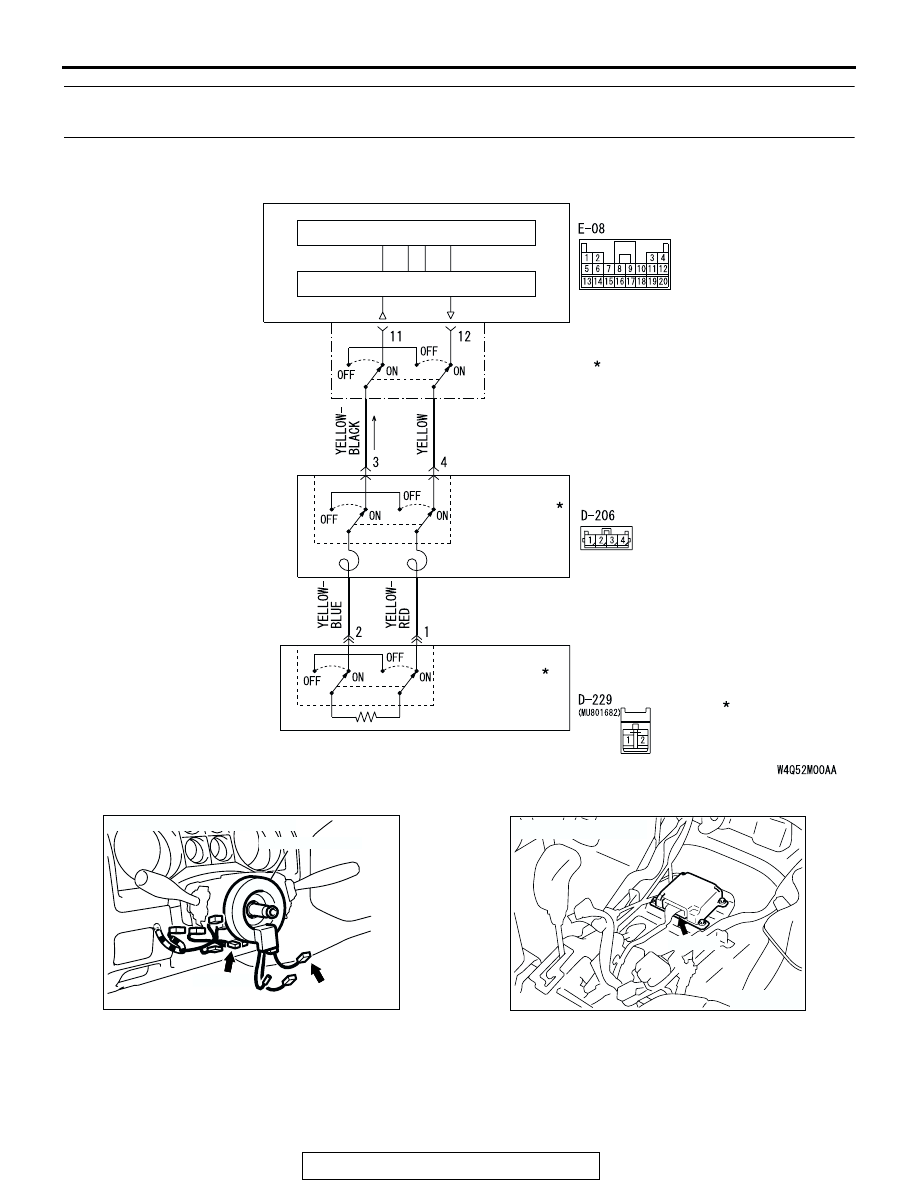
DTC 61: Driver's Air Bag Module (Squib) System Fault for Power Supply Circuit (Short-Circuited to 
Power Supply)

.

AIR BAG MODULE
(SQUIB)
(DRIVER'S SIDE)

CLOCK 
SPRING

MICROCOMPUTER

AIR BAG DRIVE CIRCUIT

SRS-ECU

CONNECTOR
LOCK SWITCH

CONNECTOR
LOCK SWITCH

CONNECTOR
LOCK SWITCH

NOTE

: CONNECTOR
  COUPLED: ON
  CONNECTOR
  UNCOUPLED: OFF

Driver's Air Bag Module (Squib) Circuit 

AC204226AD

CLOCK SPRING

D-206 (Y)

CONNECTORS: D-206, D-229

D-229

ACX01478 AG

CONNECTOR: E-08

E-08 (Y)

SRS AIR BAG DIAGNOSIS

TSB Revision

SUPPLEMENTAL RESTRAINT SYSTEM (SRS)

52B-112

CIRCUIT OPERATION

• The SRS-ECU judges how severe a collision is 

by detecting signals from the front impact sensors 
and the front air bag analog G-sensor. If the 
impact is over a predetermined level, the 
SRS-ECU outputs an ignition signal. At this time, 
if the front air bag safing G-sensor is on, the SRS 
air bag will inflate. 

• The ignition signal is input to the air bag module 

via the clock spring to inflate the air bag.

.

DTC SET CONDITIONS
This DTC is set if there is abnormal resistance 
between the input terminals of the driver's side air 
bag module (squib). However, if no DTC resets, the 
SRS warning light will be switched off (DTC will be 
retained). 

.

TROUBLESHOOTING HINTS

• Malfunction of the clock spring

• Damaged harness wires and connectors

• Short to the power supply in the driver's air bag 

module (squib) harness

• Malfunction of the SRS-ECU

.

DIAGNOSIS

Required Special Tools:

• MB991958: Scan Tool (MUT-III Sub Assembly)

• MB991824: Vehicle Communication Interface (V.C.I.)

• MB991827: MUT-III USB Cable

• MB991911: MUT-III Main Harness B (Vehicles without 

CAN communication system)

• MB991865: Dummy resister

• MB991866: Resister harness

STEP 1. Check the driver's air bag module. (Using scan 
tool MB991958, read the diagnostic trouble code)..
(1) Disconnect the negative battery terminal.
(2) By sliding the A section (in the figure) of air bag module 

connector D-229 in arrow direction, disconnect the 
connector.

(3) Connect special tool MB991865 to special tool MB991866.

CAUTION

Do not insert a test probe into the terminal from its front 
side directly as the connector contact pressure may be 
weakened.
(4) Insert special tool MB991866 into clock spring side air bag 

module connector D-229 by backprobing.

(5) Connect the negative battery terminal.
(6) Erase the diagnostic trouble code memory, and check the 

diagnostic trouble code.

Q:  Is DTC 61 out put?

YES : Go to Step 2.
NO :  Replace the driver’s air bag module (Refer to 

P.52B-217

). Then go to Step 5.

AC100441AE

D-229 AIR BAG MODULE
CONNECTOR

STEERING WHEEL

A

AC303006AD

D-229 AIR BAG
MODULE
CONNECTOR

MB991865
(DUMMY RESISTOR : 3

Ω)

MB991866 (RESISTOR 
HARNESS)

SRS AIR BAG DIAGNOSIS

TSB Revision

SUPPLEMENTAL RESTRAINT SYSTEM (SRS)

52B-113

STEP 2. Check the clock spring. (Using scan tool 
MB991958, read the diagnostic trouble code).
(1) Disconnect the negative battery terminal.
(2) Disconnect the clock spring connector D-206.
(3) Connect special tool MB991865 to special tool MB991866.

CAUTION

Do not insert a test probe into the terminal from its front 
side directly as the connector contact pressure may be 
weakened.
(4) Insert special tool MB991866 into clock spring harness 

connector D-206 (terminal No.3 and 4) by backprobing.

(5) Connect the negative battery terminal.
(6) Erase the diagnostic trouble code memory, and check the 

diagnostic trouble code.

Q:  Is DTC 61 set?

YES : Go to Step 3.
NO :  Replace the clock spring (Refer to 

P.52B-217

). Then 

go to Step 5.

AC303587

D-206 CLOCK SPRING
CONNECTOR

AD

MB991865
(DUMMY RESISTOR : 3

Ω)

MB991866 (RESISTOR 
HARNESS)

1 2

4

3

(REAR VIEW)

SRS AIR BAG DIAGNOSIS

TSB Revision

SUPPLEMENTAL RESTRAINT SYSTEM (SRS)

52B-114

STEP 3. Check the harness for short circuit to power 
supply between the SRS-ECU and the clock spring.
(1) Disconnect SRS-ECU connector E-08.

DANGER

To prevents the air bag from deploying unintention-
ally, disconnect the clock spring connector D-206 to 
short the squib circuit.

(2) Disconnect the clock spring connector D-206.
(3) Turn the ignition switch to the "ON" position.

CAUTION

Do not insert a test probe into the terminal from its front 
side directly as the connector contact pressure may be 
weakened.
(4) Measure the voltage between E-08 harness connector 

terminals 11, 12 and body ground.
Voltage should measure 0 volt.

Q: Is the measured voltage within the specified range?

YES : Erase the diagnostic trouble code memory, and check 

the diagnostic trouble code. If DTC 61 sets. replace 
the SRS-ECU (Refer to 

P.52B-215

). Then go to Step 

5.

NO :  Then go to Step 4.

ACX01478AM

CONNECTOR: E-08

E-08 (Y)

HARNESS SIDE
CONNECTOR
(REAR VIEW)

AC204226 AF

CONNECTOR: D-206

CLOCK SPRING

D-206 (Y)

HARNESS SIDE
CONNECTOR
(REAR VIEW)

1 2

4

3

AC006255

13 14 15 16 17 18 19 20

5 6 7 8 9 10 11 12

1 2

3 4

AR

E-08 HARNESS SIDE 
CONNECTOR
(REAR VIEW)


Content   ..  1192  1193  1194  1195   ..