Content .. 1118 1119 1120 1121 ..
Mitsubishi Montero (2004+). Manual - part 1120
M-ASTC DIAGNOSIS
TSB Revision
MITSUBISHI ACTIVE SKID AND TRACTION CONTROL SYSTEM
35C-191
.
CIRCUIT OPERATION
The Active skid control system operation indicator
light/Active traction control system operation indica-
tor light is connected from the ignition switch (IG1)
through multi-purpose fuse No.6 and the combina-
tion meter to the M-ASTC-ECU. The M-ASTC-ECU
turns on and off the indicator light.
.
TECHNICAL DESCRIPTION (COMMENT)
This symptom is caused by a shorted or opened
Active skid control system operation indicator
light/Active traction control system operation indica-
tor light circuit.
.
TROUBLESHOOTING HINTS (The most likely
causes for this condition:)
• Damaged wiring harness
• Burned-out bulb
• Melted fuse
• Malfunction of M-ASTC-ECU
.
DIAGNOSIS
Required Special Tool:
• MB991223: Harness Set
AC203901AG
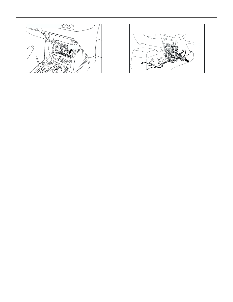
CONNECTOR: E-121
E-121
AC204548
E-122
AO
CONNECTOR: E-122