Mitsubishi Montero (2004+). Manual - part 1113


  Index      Mitsubishi     Mitsubishi Montero - service repair manual 2004 year


Search            


Content   ..  1111  1112  1113  1114   ..


Mitsubishi Montero (2004+). Manual - part 1113


M-ASTC DIAGNOSIS

TSB Revision

MITSUBISHI ACTIVE SKID AND TRACTION CONTROL SYSTEM

35C-163

STEP 31. Check for short circuit at the M-ASTC-ECU. 
Check at intermediate connector E-122.

CAUTION

Before checking CAN bus lines and their interconnected 
components, "ground" yourself, by touching a metal 
object such as an unpainted pipe, this will discharge any 
potentially damaging static that may have built up.

CAUTION

When measuring resistance value or voltage in CAN bus 
lines, use a digital multimeter. If not using a digital multim-
eter, the equipments, which are connected through the 
CAN communication lines, may be damaged.
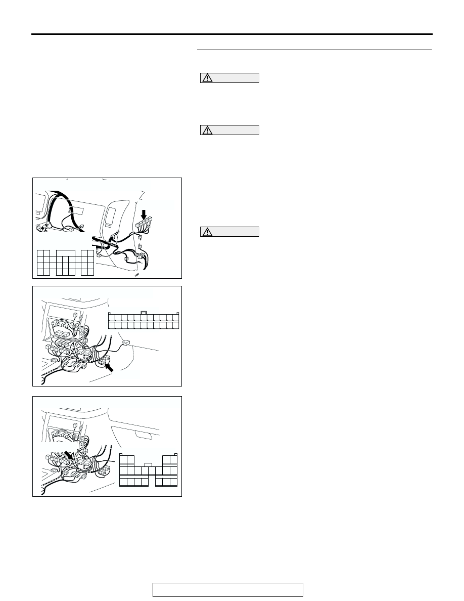
(1) Disconnect intermediate connectors E-122, E-123, and 

power control module connector D-134, and measure the 
resistance at the female intermediate connector (control 
panel wiring harness side).

(2) Turn the ignition switch to the LOCK (OFF) position.

CAUTION

Disconnect the negative battery terminal when measuring 
the resistance value in the CAN bus line. If you fail to do 
so, the equipments, which are connected through the CAN 
communication lines, may be damaged.
(3) Disconnect the negative battery terminal.

AC204171

CONNECTOR: D-134

HARNESS SIDE

D-134(GR)

D-134(GR)

AE

80

87

73

66

67

65
74

81

75

82

6261

72

68

69

70

71

78

85

77

8483

76

79

86

63

64

8988

AC204176

CONNECTOR: E-122

E-122(L)

FEMALE SIDE

E-122(L)

AG

11

22

10

21

9

20

8

19

7

18

6

17

5

16

4

15

3

14

2

13

1

12

AC204176

CONNECTOR: E-123

AR

E-123(GR)

2

6

14

7

9 8

10

4

12

3

11

19

16

1817

15

1

5

13

E-123(GR)

M-ASTC DIAGNOSIS

TSB Revision

MITSUBISHI ACTIVE SKID AND TRACTION CONTROL SYSTEM

35C-164

CAUTION

Always use the test harness when measuring the voltage 
or resistance value at the female connector. If you fail to do 
so, connectors may be damaged.
(4) Measure the resistance between intermediate connector 

E-122 terminals 9 and 20.

• The resistance should measure 120 ± 12 ohms.

Q: Does the resistance measure 120 

± 12 ohms?

YES : Go to Step 32.
NO :  Replace the control wiring harness assembly.

AC204581

FEMALE CONNECTOR: E-122

TEST 
HARNESS

AD

TEST 
HARNESS

11

22

10

21

9

20

8

19

7

18

6

17

5

16

4

15

3

14

2

13

1

12

M-ASTC DIAGNOSIS

TSB Revision

MITSUBISHI ACTIVE SKID AND TRACTION CONTROL SYSTEM

35C-165

STEP 32. Check power control module connector D-134, G 
and yaw rate sensor connector E-126 and intermediate 
connector E-123.

CAUTION

If there is a problem in the connector(s) (including termi-
nals) or wire(s) of the instrument panel wiring harness 
assembly (the wiring harness connected to the steering 
wheel sensor, the data link connector and the resistor) and 
the transmission wiring harness assembly (the wiring har-
ness connected to the G and yaw rate sensor connector 
and intermediate connector E-123), cut and repair the 
defective wire so that the frayed end of the twisted wire 
should be within 10 cm (4.0 inches). If it exceeds 10 cm (4.0 
inches), twist the wiring harness just like the original 
twisted wire. If the frayed end exceeds 10 cm (4.0 inches), 
a communication error may be caused.

AC204171

CONNECTOR: D-134

HARNESS SIDE

D-134(GR)

D-134(GR)

AE

80

87

73

66

67

65
74

81

75

82

6261

72

68

69

70

71

78

85

77

8483

76

79

86

63

64

8988

AC204176

CONNECTOR: E-123

AR

E-123(GR)

2

6

14

7

9 8

10

4

12

3

11

19

16

1817

15

1

5

13

E-123(GR)

AC204175

CONNECTOR: E-126

HARNESS SIDE

E-126(GR)

E-126(GR)

AB

FLOOR 
CONSOLE

1

2

4 3

AC203824

CONNECTOR

TWISTED WIRE

AB

10 cm
 (4.0 inches)

M-ASTC DIAGNOSIS

TSB Revision

MITSUBISHI ACTIVE SKID AND TRACTION CONTROL SYSTEM

35C-166

CAUTION

If there is a problem in the CAN bus line or the connectors 
on the control wiring harness assembly (the wiring har-
ness connected to the M-ASTC-ECU, the power control 
module and intermediate connector E-123), do not attempt 
to repair the wiring harness or connector(s), but replace 
the wiring harness assembly. If a wire is added or the con-
nector(s) are repaired, an error in the CAN communication 
may be caused.
Q: Are power control module connector D-134, G and yaw 

rate sensor connector E-126 and intermediate 
connector E-123 in good condition?
YES : 
Go to Step 33.
NO (If there is a problem at the transmission wiring 
harness assembly side) : 
Repair or replace the connector.
NO (If there is a problem at the control wiring harness 
assembly side) : 
Replace the control wiring harness 

assembly.


Content   ..  1111  1112  1113  1114   ..