Mitsubishi Montero (2004+). Manual - part 1105


  Index      Mitsubishi     Mitsubishi Montero - service repair manual 2004 year


Search            


Content   ..  1103  1104  1105  1106   ..


Mitsubishi Montero (2004+). Manual - part 1105


M-ASTC DIAGNOSIS

TSB Revision

MITSUBISHI ACTIVE SKID AND TRACTION CONTROL SYSTEM

35C-131

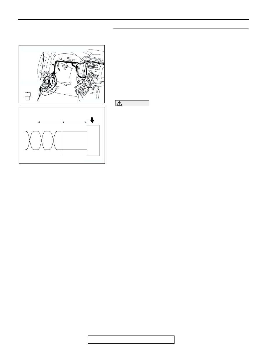
STEP 4. Check resistor connector D-130.

CAUTION

If there is a problem in the connector(s) (including termi-
nals) or wire(s) of the instrument panel wiring harness 
assembly (the wiring harness connected to the steering 
wheel sensor, the data link connector and the resistor) and 
the transmission wiring harness assembly (the wiring har-
ness connected to the G and yaw rate sensor connector 
and intermediate connector E-123), cut and repair the 
defective wire so that the frayed end of the twisted wire 
should be within 10 cm (4.0 inches). If it exceeds 10 cm (4.0 
inches), twist the wiring harness just like the original 
twisted wire. If the frayed end exceeds 10 cm (4.0 inches), 
a communication error may be caused.
Q: Is resistor connector D-130 in good condition?

YES : Go to Step 5.
NO :  Repair or replace the connector, and then go to Step 

5.

AC204170

CONNECTOR: D-130

HARNESS SIDE

AQ

1
2

AC203824

CONNECTOR

TWISTED WIRE

AB

10 cm
 (4.0 inches)

M-ASTC DIAGNOSIS

TSB Revision

MITSUBISHI ACTIVE SKID AND TRACTION CONTROL SYSTEM

35C-132

STEP 5. Check the terminator resistor. Measure at resistor 
connector D-130.

CAUTION

Before checking CAN bus lines and their interconnected 
components, "ground" yourself, by touching a metal 
object such as an unpainted pipe, this will discharge any 
potentially damaging static that may have built up.
(1) Disconnect resistor connector D-130, and measure the 

resistance at the component-side connector.

(2) Measure the resistance between resistor connector D-130 

terminals 1 and 2.

• The resistance should measure 120 ± 20 ohms.

Q: Does the resistance measure 120 

± 20 ohms?

YES : Go to Step 6.
NO :  Replace the resistor, and then go to Step 6.

STEP 6. Check M-ASTC-ECU connector E-121.

CAUTION

If there is a problem in the CAN bus line or the connectors 
on the control wiring harness assembly (the wiring har-
ness connected to the M-ASTC-ECU, the power control 
module and intermediate connector E-123), do not attempt 
to repair the wiring harness or connector(s), but replace 
the wiring harness assembly. If a wire is added or the con-
nector(s) are repaired, an error in the CAN communication 
may be caused.
Q: Is M-ASTC-ECU connector E-121 in good condition?

YES : Go to Step 7.
NO :  Replace the control wiring harness and then go to 

Step 7. If the resistor or its connector is repaired or 
replaced, repair or replace the connector and then 
retest the system.

AC204170

CONNECTOR: D-130

COMPONENT  
SIDE

AS

1
2

AC204579

1
2

COMPONENT SIDE: D-130

TEST 
HARNESS

AB

TEST 
HARNESS

AC204176

CONNECTOR: E-121

HARNESS SIDE

AC

71

77

83

72

78

84

73

79

85

74

80

75

81

86

76

82

87

M-ASTC DIAGNOSIS

TSB Revision

MITSUBISHI ACTIVE SKID AND TRACTION CONTROL SYSTEM

35C-133

STEP 7. Check the terminator resistor inside the 
M-ASTC-ECU. Measure at M-ASTC-ECU connector E-121.

CAUTION

Before checking CAN bus lines and their interconnected 
components, "ground" yourself, by touching a metal 
object such as an unpainted pipe, this will discharge any 
potentially damaging static that may have built up.
(1) Disconnect M-ASTC-ECU connector E-121, and measure 

the resistance at the component-side connector.

(2) Measure the resistance between M-ASTC-ECU connector 

E-12 terminals 83 and 84.

• The resistance should measure 120 ± 20 ohms.

Q: Does the resistance measure 120 

± 20 ohms?

YES : Go to Step 8.
NO :  Replace the M-ASTC-ECU and then go to Step 8. If 

the resistor or its connector is repaired or replaced, 
replace the M-ASTC-ECU and then retest the system.

AC204176

CONNECTOR: E-121

COMPONENT 
SIDE

AE

76

82

87

75

81

86

74

80

85

73

79

72

78

84

71

77

83

AC204581

COMPONENT SIDE: E-121

TEST 
HARNESS

AB

TEST 
HARNESS

76

82

87

75

81

86

74

80

85

73

79

72

78

84

71

77

83

M-ASTC DIAGNOSIS

TSB Revision

MITSUBISHI ACTIVE SKID AND TRACTION CONTROL SYSTEM

35C-134

STEP 8. Check intermediate connector E-122.

CAUTION

If there is a problem in the connector(s) (including termi-
nals) or wire(s) of the instrument panel wiring harness 
assembly (the wiring harness connected to the steering 
wheel sensor, the data link connector and the resistor) and 
the transmission wiring harness assembly (the wiring har-
ness connected to the G and yaw rate sensor connector 
and intermediate connector E-123), cut and repair the 
defective wire so that the frayed end of the twisted wire 
should be within 10 cm (4.0 inches). If it exceeds 10 cm (4.0 
inches), twist the wiring harness just like the original 
twisted wire. If the frayed end exceeds 10 cm (4.0 inches), 
a communication error may be caused.

CAUTION

If there is a problem in the CAN bus line or the connectors 
on the control wiring harness assembly (the wiring har-
ness connected to the M-ASTC-ECU, the power control 
module and intermediate connector E-123), do not attempt 
to repair the wiring harness or connector(s), but replace 
the wiring harness assembly. If a wire is added or the con-
nector(s) are repaired, an error in the CAN communication 
may be caused.
Q: Is intermediate connector E-122 in good condition?

YES : Go to Step 9.
NO (If there is a defect at the instrument panel wiring 
harness assembly side) : 
Repair or replace the connector, 

and then go to Step 9.

NO (If the resistor is replaced) : Repair its connector and 

then retest the system.

NO (If there is a problem at the control wiring harness 
assembly side) : 
Replace the control wiring harness 

assembly and then go to Step 9.

NO (If the resistor is replaced) : Repair its connector and 

then retest the system.

AC204176

CONNECTOR: E-122

E-122(L)

E-122(L)

AD

1

12

2

13

3

14

4

15

5

16

6

17

7

18

8

19

9

20

10

21

11

22

AC203824

CONNECTOR

TWISTED WIRE

AB

10 cm
 (4.0 inches)


Content   ..  1103  1104  1105  1106   ..