Mitsubishi Montero (2004+). Manual - part 1085


  Index      Mitsubishi     Mitsubishi Montero - service repair manual 2004 year


Search            


Content   ..  1083  1084  1085  1086   ..


Mitsubishi Montero (2004+). Manual - part 1085


M-ASTC DIAGNOSIS

TSB Revision

MITSUBISHI ACTIVE SKID AND TRACTION CONTROL SYSTEM

35C-51

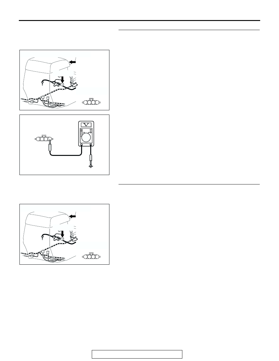
STEP 4. Check the power supply system from the ignition 
switch (IG1) to the G and yaw rate sensor. Measure at G 
and yaw rate sensor connector E-126.

(1) Disconnect G and yaw rate sensor connector E-126, and 

measure the voltage at the harness-side connector.

(2) Turn the ignition switch to the "ON" position.

(3) Measure the voltage between G and yaw rate sensor 

connector E-126 terminal 1 and body ground.

• The voltage should measure battery voltage (approxi-

mately 12 volts).

Q: Does the voltage measure battery voltage 

(approximately 12 volts)?
YES : 
Go to Step 6.
NO :  Go to Step 5.

STEP 5. Check the wiring harness between G and yaw rate 
sensor connector E-126 terminal 1 and the ignition switch 

(IG1).

AC204175

CONNECTOR: E-126

HARNESS SIDE

E-126(GR)

E-126(GR)

AB

FLOOR 
CONSOLE

1

2

4 3

AC204580

HARNESS SIDE: E-126

AO

1

2

4 3

AC204175

CONNECTOR: E-126

HARNESS SIDE

E-126(GR)

E-126(GR)

AB

FLOOR 
CONSOLE

1

2

4 3

M-ASTC DIAGNOSIS

TSB Revision

MITSUBISHI ACTIVE SKID AND TRACTION CONTROL SYSTEM

35C-52

NOTE: Also check joint connector D-01 and junction block con-
nector D-208 and D-212 and intermediate connector E-11 for 
loose, corroded, or damaged terminals, or terminals pushed 
back in the connectors. If joint connector D-01 or junction block 
connector D-208 or D-212 or intermediate connector E-11 are 
damaged, repair or replace the damaged component(s) as 
described in GROUP 00E, Harness Connector Inspection 

P.00E-2

. If the connector has been repaired or replaced, go to 

Step 9.
Q: Is the wiring harness between G and yaw rate sensor 

connector E-126 terminal 1 and the ignition switch (IG1) 
in good condition?
YES : 
Go to Step 9.
NO :  Repair the wiring harness, and then go to Step 9.

AC204170

CONNECTOR: D-01

AB

9 10

8

6 7

31 32

30

29

18 19 20 21

5

4

2

1

3

27

26

24

23

25

12 13 14 15 16 17

28

11
22
33

AC204191

CONNECTORS: D-208, D-212

D-208

AN

HARNESS SIDE

HARNESS SIDE

D-212

D-208

D-212

1

2

3

5

6

4

7 6 5

2 1

9 8

11 10

4 3

AC204176

CONNECTOR: E-11

AB

3

10

16

9

7 8

6

1

4

2

5

11

14

1213

15

M-ASTC DIAGNOSIS

TSB Revision

MITSUBISHI ACTIVE SKID AND TRACTION CONTROL SYSTEM

35C-53

STEP 6. Check G and yaw rate sensor for ground circuit. 
Measure at G and yaw rate sensor connector E-126.

(1) Disconnect G and yaw rate sensor connector E-126, and 

measure the resistance at the harness-side connector.

(2) Measure the resistance between G and yaw rate sensor 

connector E-126 terminal 4 and body ground.

• The resistance should measure 2 ohms or less.

Q: Does the resistance measure 2 ohms or less?

YES : Go to Step 8.
NO :  Go to Step 7.

STEP 7. Check the wiring harness between G and yaw rate 
sensor connector E-126 terminal 4 and body ground.

Q: Is the wiring harness between G and yaw rate sensor 

connector E-126 terminal 4 and the body ground in 
good condition?
YES : 
Go to Step 9.
NO :  Repair the wiring harness, and then go to Step 9.

STEP 8. Replace the G and yaw rate sensor (Recheck for 
diagnostic trouble code).

Replace the G and yaw rate sensor, and check that the DTC 
sets.
Q: Does DTC 67 reset?

YES : Replace the M-ASTC-ECU, and then go to Step 9.
NO :  The procedure is complete.

STEP 9. Recheck for diagnostic trouble code.
Q: Does DTC 67 reset?

YES : Return to Step 1.
NO :  The procedure is complete.

AC204175

CONNECTOR: E-126

HARNESS SIDE

E-126(GR)

E-126(GR)

AB

FLOOR 
CONSOLE

1

2

4 3

AC204581

HARNESS SIDE: E-126

AT

1

2

4 3

AC204175

CONNECTOR: E-126

HARNESS SIDE

E-126(GR)

E-126(GR)

AB

FLOOR 
CONSOLE

1

2

4 3

M-ASTC DIAGNOSIS

TSB Revision

MITSUBISHI ACTIVE SKID AND TRACTION CONTROL SYSTEM

35C-54

DTC 75: Defective transfer switch

.

CIRCUIT OPERATION
If the transfer gear is engaged, a relevant switch is 
turned on. When the switch is turned on, the current 
from the M-ASTC-ECU is grounded. 

.

M-ASTC DTC SET CONDITION
DTC 75 is set when the 2WD/4WD detection switch, 
the center differential detection switch, the 2WD 
detection switch, 4LLc detection switch or the 4H 
detection switch or their relevant circuits is defective.

.

TROUBLESHOOTING HINTS
The most likely causes for DTC 75 to set are:

• The 2WD/4WD detection switch is defective.

Transfer Switch Circuit

AC204395

CONNECTORS: C-05, C-06, C-10, C-11, C-12

C-05(BR)

AD

C-06(B)

C-11(W)

C-12(BR)

C-10(B)

AC204176

CONNECTORS: E-121, E-123

E-121

AO

E-123(GR)


Content   ..  1083  1084  1085  1086   ..