Content .. 1068 1069 1070 1071 ..
Mitsubishi Montero (2004+). Manual - part 1070
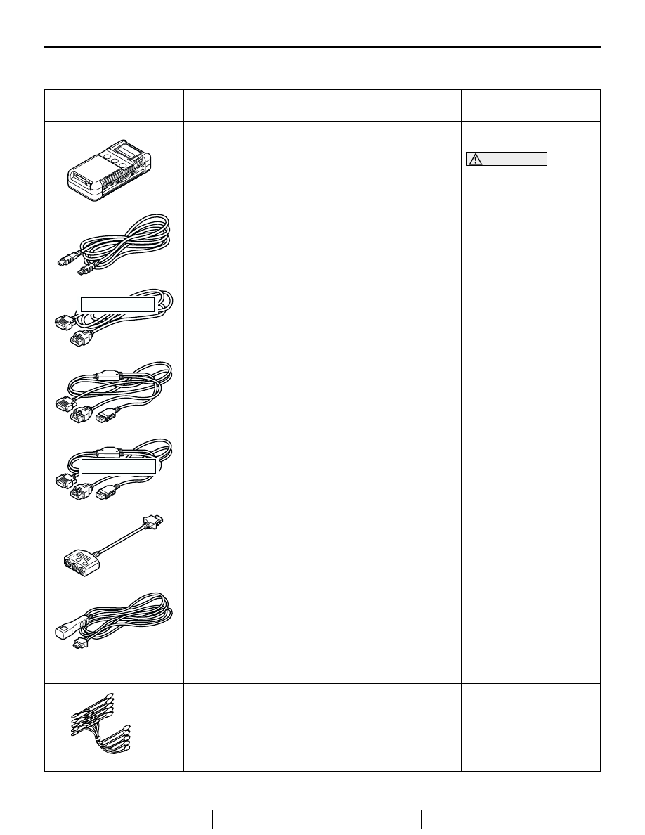
SPECIAL TOOLS
TSB Revision
ANTI-LOCK BRAKING SYSTEM (ABS)
35B-123
SPECIAL TOOLS
M1352000600727
TOOL
TOOL NUMBER AND
NAME
SUPERSESSION
APPLICATION
MB991958
A: MB991824
B: MB991827
C: MB991910
D: MB991911
E: MB991914
F: MB991825
G: MB991826
MUT-III sub assembly
A: Vehicle
communication
interface (V.C.I.)
B: MUT-III USB cable
C: MUT-III main harness
A (Vehicles with CAN
communication
system)
D: MUT-III main harness
B (Vehicles without
CAN communication
system)
E: MUT-III main harness
C (for Daimler Chrysler
models only)
F: MUT-III measurement
adapter
G: MUT-III trigger
harness
MB991824-KIT
NOTE: G: MB991826
MUT-III trigger harness is
not necessary when
pushing V.C.I ENTER key
Checking diagnostic
trouble codes
CAUTION
MUT-III main harness B
(MB991911) should be
used. MUT-III main
harness A and C should
not be used for this
vehicle.
MB991348
Test harness set
MB991496-OD
For checking of G and
yawrate sensor
MB991910
MB991826
MB991958
MB991911
MB991914
MB991824
MB991827
MB991825
DO NOT USE
A
B
C
D
E
F
G
DO NOT USE
MB991348